Valve Drawing Symbols
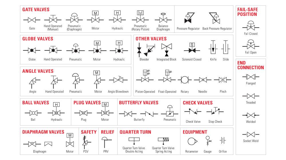
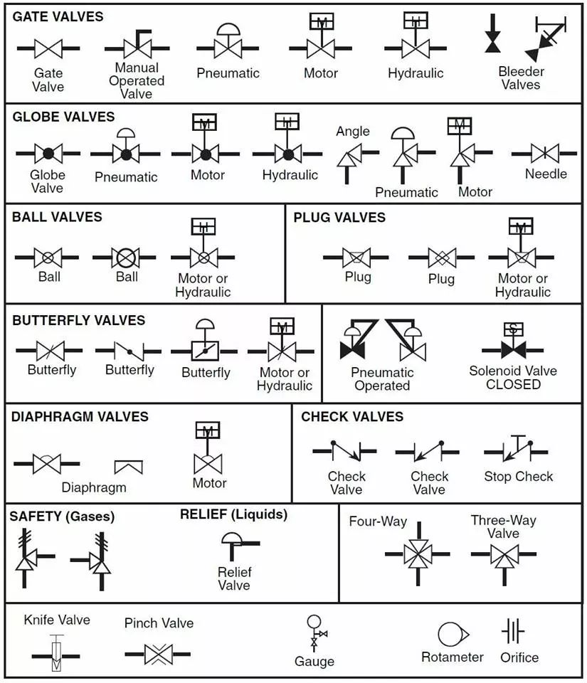
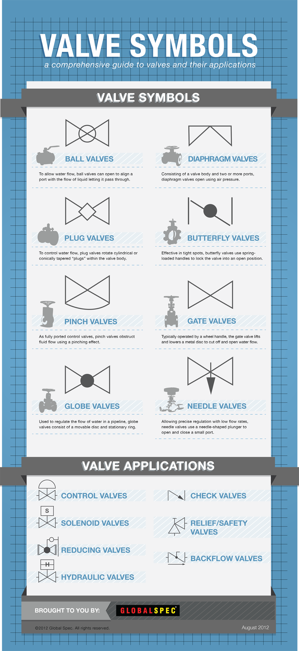
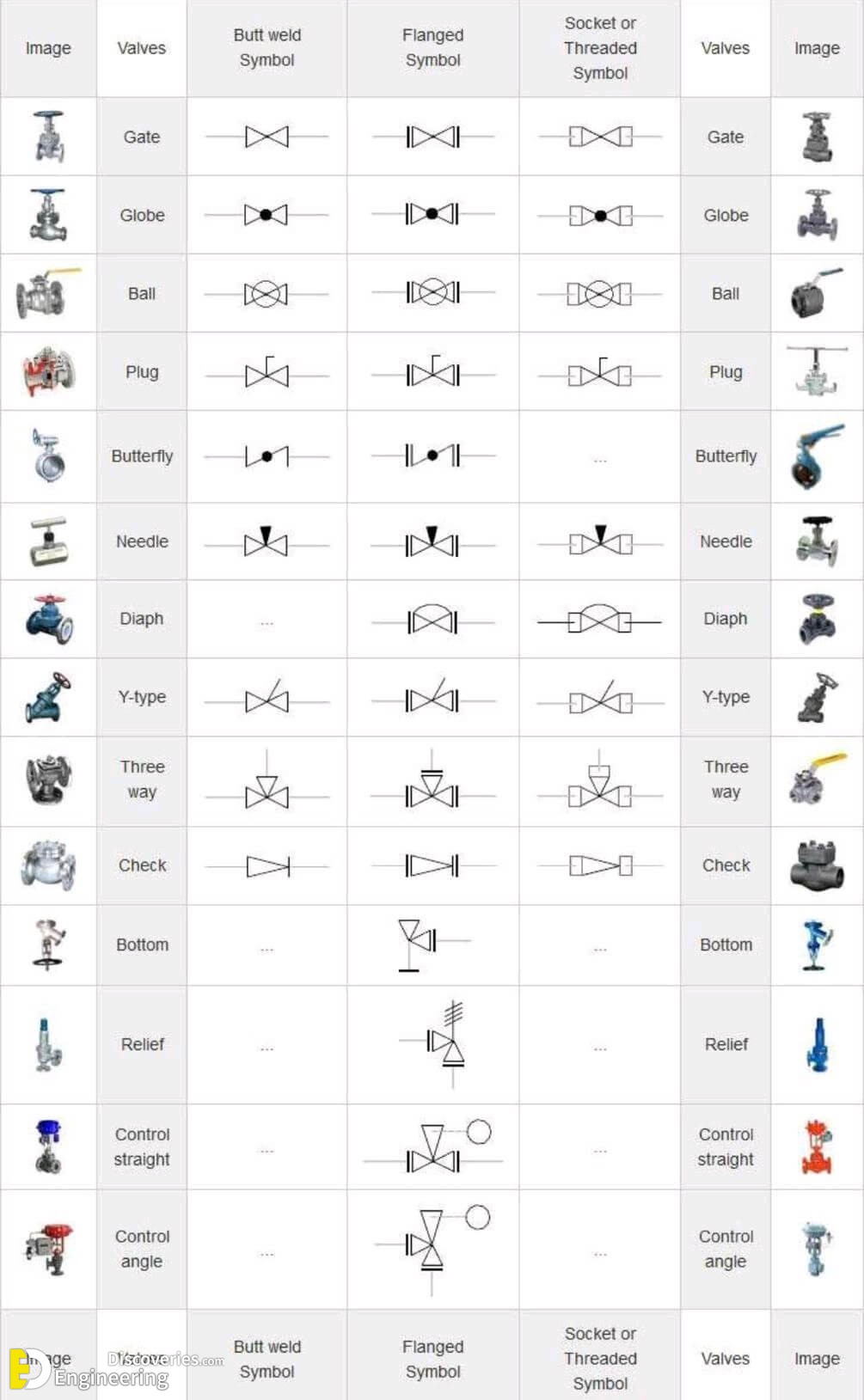
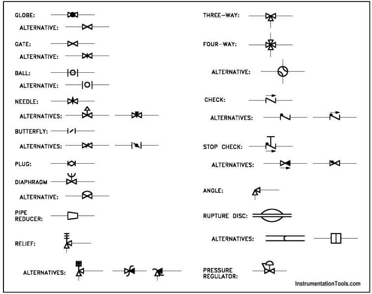
Valve Drawing Symbols - Figure 1 shows the symbols that depict the major valve types. Web a piping and instrumentation diagram (p&id) is a graphic representation of a process system that includes the piping, vessels, control valves, instrumentation, and other process components and equipment in the system. A valve regulates, directs, or controls the flow of a fluid by opening, closing, or partially obstructing passageways in a piping system.this category includes rotameters, orifices, and other types of valves. They include the vessels, piping, control valves, instrumentation, equipment, and other components involved in. Rotate a disc or ellipse about a shaft extending across the diameter of an orifice (for example, a butterfly or ball valve). Web what does piping & instrumentation diagram (p& id) imply? A valve is a device that regulates, directs or controls the flow of a fluid (gases, liquids, fluidized solids, or slurries) by opening, closing, or partially obstructing various passageways. In such cases, information concerning the valve type may be conveyed by the component How do i read valve symbols and p&id diagrams? Valves are technically fittings, but are usually discussed as a separate category. A valve is a device that regulates, directs or controls the flow of a fluid (gases, liquids, fluidized solids, or slurries) by opening, closing, or partially obstructing various passageways. Web here is a list of symbols for various types of valves used in process industry. 1 provides symbols for strainers, separators, and filters. These symbols can represent actuators, sensors, and. In such cases, information concerning the valve type may be conveyed by the component P&id symbols for piping valves. 2 provides symbols for valves. How do i read valve symbols and p&id diagrams? These details may include the size, function, pressure rating, and. They include the vessels, piping, control valves, instrumentation, equipment, and other components involved in. 1 provides symbols for strainers, separators, and filters. You can also see the symbols for pneumatic, hydraulic, and capillary lines. Downloadable pdf of valve, actuator and other popular p&id symbols. It includes details like piping, vessels, control valves, instruments, and process components and equipment. Web what does piping & instrumentation diagram (p& id) imply? Downloadable pdf of valve, actuator and other popular p&id symbols. What is a piping & instrumentation diagram (p&id)? It should be noted that globe and gate valves will often be depicted by the same valve symbol. In such cases, information concerning the valve type may be conveyed by the component The process flow diagram (pfd), which explains a relatively typical flow of plant processes about significant equipment of a plant facility, and the piping and instrumentation diagram have a. A valve is a device that regulates, directs or controls the flow of a fluid (gases, liquids, fluidized solids, or slurries) by opening, closing, or partially obstructing various passageways. Standard practice. Web main process lines are shown as dark black lines, whereas minor lines are shown as thin black lines. Reading p&id with valve symbols. An engineer may also include specific details below the control valve symbol. In the realm of valve manufacturing, where precision engineering meets functional necessity, the comprehension of basic valve symbols emerges as an essential competency for. In such cases, information concerning the valve type may be conveyed by the component In the realm of valve manufacturing, where precision engineering meets functional necessity, the comprehension of basic valve symbols emerges as an essential competency for industry professionals. In this article, we highlight some of the most common p&id valve symbols, process lines, end connections and other vital. Figure 1 shows the symbols that depict the major valve types. A piping and instrumentation diagram (p&id) is a comprehensive graphical representation of a process system. Standard practice for piping system drawing symbols. Figure 1 shows the symbols that depict the major valve types. Web a piping and instrumentation diagram (p&id) is a graphic representation of a process system that. In this article, we highlight some of the most common p&id valve symbols, process lines, end connections and other vital components. Web what does piping & instrumentation diagram (p& id) imply? In such cases, information concerning the valve type may be conveyed by the component A valve is a device that regulates, directs or controls the flow of a fluid. Reading piping and instrumentation diagrams (p&ids) with valve symbols is a fundamental skill for engineers, technicians, and operators involved in the design, operation, and. P&id symbols for piping valves. Reading p&id with valve symbols. Standard practice for piping system drawing symbols. Electric signals are shown as a dotted line, and electromagnetic signals are shown as a wave on a solid. Web valve symbols valves are used to control the direction, flow rate, and pressure of fluids. Such as ball valve, plug valve, refile valve, gate valve, check valve, butterfly valve. Figure 1 shows the symbols that depict the major valve types. You can also see the symbols for pneumatic, hydraulic, and capillary lines. The process flow diagram (pfd), which explains a relatively typical flow of plant processes about significant equipment of a plant facility, and the piping and instrumentation diagram have a. The symbol typically consists of the actual valve symbol, and the actuation method such as pneumatic, hydraulic, or electric. Valves are used to control the direction, flow rate, and pressure of fluids. Web piping and instrumentation diagrams (p&ids) use specific symbols to show the connectivity of equipment, sensors, and valves in a control system. A piping and instrumentation diagram (p&id) is a comprehensive graphical representation of a process system. Web learn about types of valve symbols used in p&id and iso drawing. They include the vessels, piping, control valves, instrumentation, equipment, and other components involved in. Slide a flat, cylindrical, or spherical surface across an orifice (for example, gate and plug valves). How do i read valve symbols and p&id diagrams? Web isometric drawing symbols for piping valves. These symbols can represent actuators, sensors, and controllers and may be. P&id symbols for piping valves.
Valve Symbols 101 A Comprehensive Guide
The Most Common Control Valve Symbols on a P&ID Kimray
Valve Symbols for P&IDs The Engineering Concepts

Types Of Valves, Their Functions And Symbols Engineering Discoveries

Valve Symbols in P&ID Ball Valve, Relief Valve and more

Drawing Symbol for Valves and Joints Engineer Diary
Valve Symbols
Types Of Valves, Their Functions And Symbols Engineering Discoveries

Valves Symbols used in P&ID and Piping Isometric drawings YouTube
Symbol For Valve In Schematic
An Engineer May Also Include Specific Details Below The Control Valve Symbol.
Rotate A Disc Or Ellipse About A Shaft Extending Across The Diameter Of An Orifice (For Example, A Butterfly Or Ball Valve).
To Read And Understand Engineering Fluid Diagrams And Prints, Usually Referred To As P&Ids, An Individual Must Be Familiar With The Basic Symbols.
Web Valve Symbols 1.
Related Post: