What Type Of Drawing Is A Ladder Diagram
What Type Of Drawing Is A Ladder Diagram - The ability to read and understand electrical ladder drawings, schematics and diagrams. Web ladder logic (also known as ladder diagram or ld) is a programming language used to program a plc (programmable logic controller). A _____________________ is a type of schematic that represents circuits concisely and is. Web by peter june 28, 2015. Web basics of ladder logic symbols. They are called “ladder” diagrams because they are constructed in a way that resembles a ladder with two vertical rails and rungs between. From appendix 11, the p ka for p ‐nitrophenol is 7.15. What is ladder logic & ladder diagram? In this animated object, learners examine the design of a ladder circuit that provides manual control to a water pumping system. These diagrams documented how connections between devices were made on relay panels; Web by peter june 28, 2015. Boosting your proficiency in ladder diagrams, logic and plc programming. In this animated object, learners examine the design of a ladder circuit that provides manual control to a water pumping system. A ladder diagram, shown in figure 3, is a diagram that explains the logic of the electrical circuit or system using standard nema. They are called “ladder” diagrams because they are constructed in a way that resembles a ladder with two vertical rails and rungs between. These diagrams documented how connections between devices were made on relay panels; A guide to visual plc programming. The two vertical lines (wires) that serve as a boundary for the control system and deliver the. Web by. They are called “ladder” diagrams because they resemble a ladder, with two vertical rails (supply power) and as many “rungs” (horizontal lines) as there are control circuits to represent. A guide to visual plc programming. Ladder logic symbols represent various components and operations in a control system, such as inputs, outputs, logical operations, timers, counters, and more. Web what type. Web what method is used to determine the initial state of each output in the ladder diagram? Web what is a ladder diagram? It is a graphical plc programming language which expresses logic operations with symbolic notation. A beginner’s guide to plc visualization. A ladder diagram is used to point out relationships between circuit components, not the actual location of. Web ladder diagrams are specialized schematics commonly used to document industrial control logic systems. To draw a ladder diagram for a weak base, we simply draw the ladder diagram for its conjugate weak acid. Ladder logic is one of the top 5 most popular types of plc programming languages used in manufacturing environments. Web this video illustrates an effective way. Web the structure behind ladder logic is based on the electrical ladder diagrams that were used with relay logic. They are called “ladder” diagrams because they resemble a ladder, with two vertical rails (supply power) and as many “rungs” (horizontal lines) as there are control circuits to represent. Web the drawing is called a ladder drawing because it resembles a. What is ladder logic & ladder diagram? It is a graphical plc programming language which expresses logic operations with symbolic notation. Web ladder diagrams are specialized schematics commonly used to document industrial control logic systems. The ability to read and understand electrical ladder drawings, schematics and diagrams. Web by peter june 28, 2015. The two vertical lines are called rails and attach to opposite poles of a power supply, usually 120 volts ac. To draw a ladder diagram for a weak base, we simply draw the ladder diagram for its conjugate weak acid. They are called “ladder” diagrams because they resemble a ladder, with two vertical rails (supply power) and as many “rungs”. Every ladder symbol represents a certain ladder instruction. Two vertical control rails and horizontal logic rungs make up the ladder diagrams to form what appears like a ladder. Web ladder diagrams are specialized schematics commonly used to document industrial control logic systems. What is ladder logic & ladder diagram? Web a ladder diagram is a type of schematic diagram used. A _____________________ is a type of schematic that represents circuits concisely and is. The electric components or miniature. They are called “ladder” diagrams because they resemble a ladder, with two vertical rails (supply power) and as many “rungs” (horizontal lines) as there are control circuits to represent. The two vertical lines (wires) that serve as a boundary for the control. A ladder diagram is used to point out relationships between circuit components, not the actual location of the components. Web by peter june 28, 2015. By terry bartelt terry fleischman. Web ladder diagrams (sometimes called ladder logic) are a type of electrical notation and symbology frequently used to illustrate how electromechanical switches and relays are interconnected. Students also study modifications to the circuit as the complexity of the system increases. What is ladder logic & ladder diagram? Boosting your proficiency in ladder diagrams, logic and plc programming. Ladder logic is one of the top 5 most popular types of plc programming languages used in manufacturing environments. A ladder diagram, shown in figure 3, is a diagram that explains the logic of the electrical circuit or system using standard nema or iec symbols. Web this video illustrates an effective way of interpreting and understanding a basic ladder diagram for beginners. They are called “ladder” diagrams because they resemble a ladder, with two vertical rails (supply power) and as many “rungs” (horizontal lines) as there are control circuits to represent. Web ladder diagram symbols are the building blocks of ladder diagrams and they are also called ladder logic symbols. Web ladder diagrams are specialized schematics commonly used to document industrial control logic systems. The electric components or miniature. A beginner’s guide to plc visualization. Web what is a ladder diagram?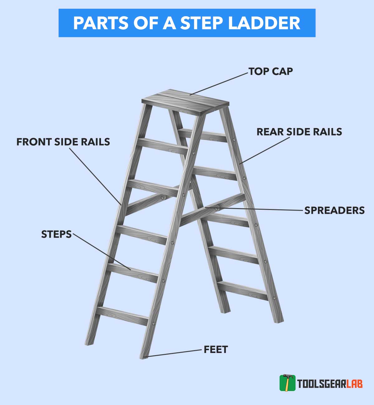
Parts Of A Ladder With Detailed Diagram Picture ToolsGearLab
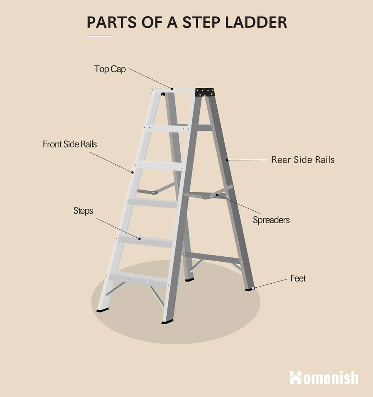
Parts of a Ladder (2 Diagrams For Step Ladder & Extension Ladder
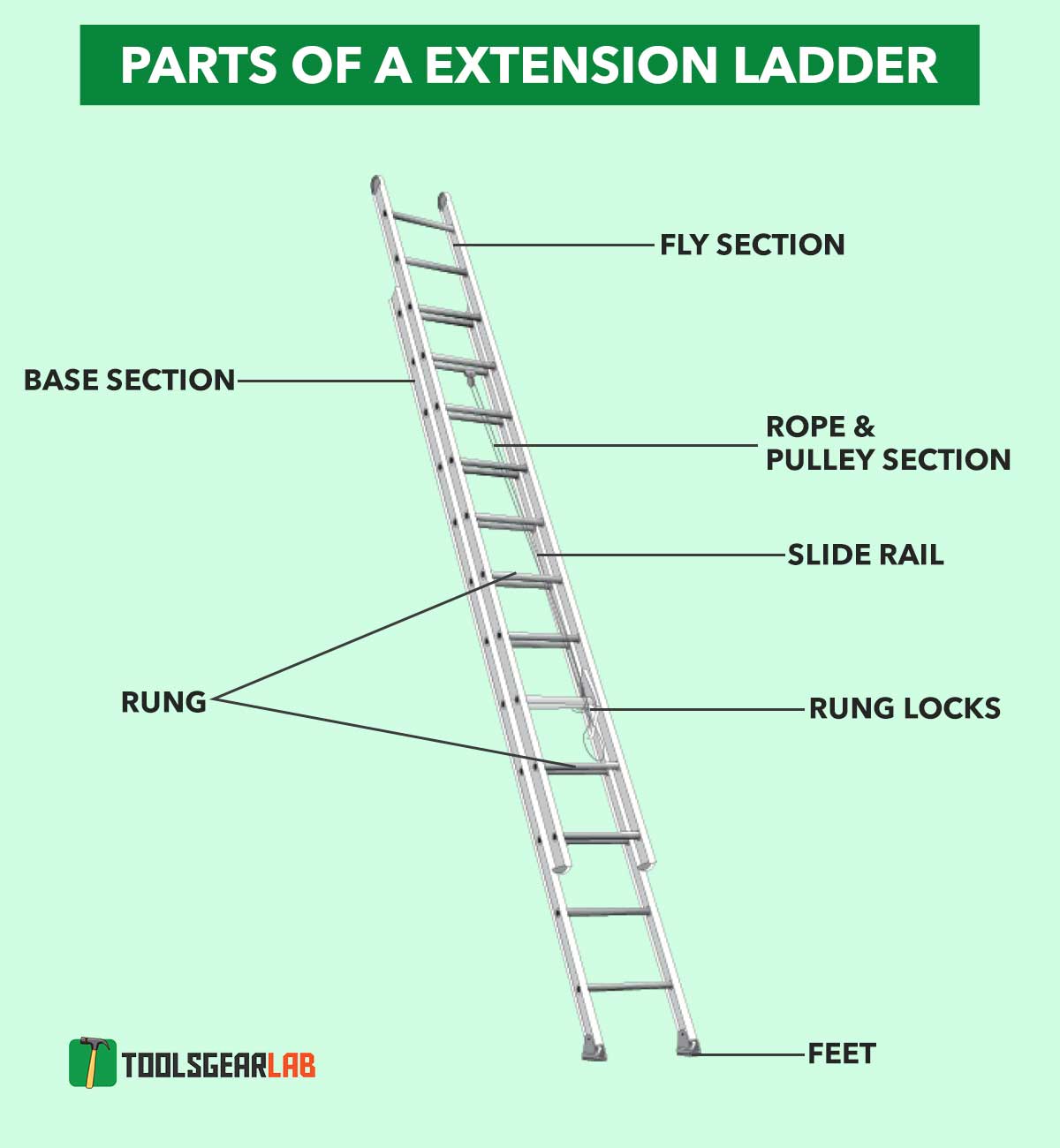
Parts Of A Ladder With Detailed Diagram Picture ToolsGearLab
How to draw a Ladder Ladder drawing step by step Easy Ladder
![[DIAGRAM] Drawing Ladder Diagram](https://www.homestratosphere.com/wp-content/uploads/2018/02/03_Step-Up-Ladder.jpg)
[DIAGRAM] Drawing Ladder Diagram
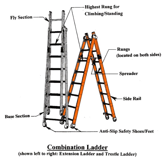
Ladders 101 American Ladder Institute
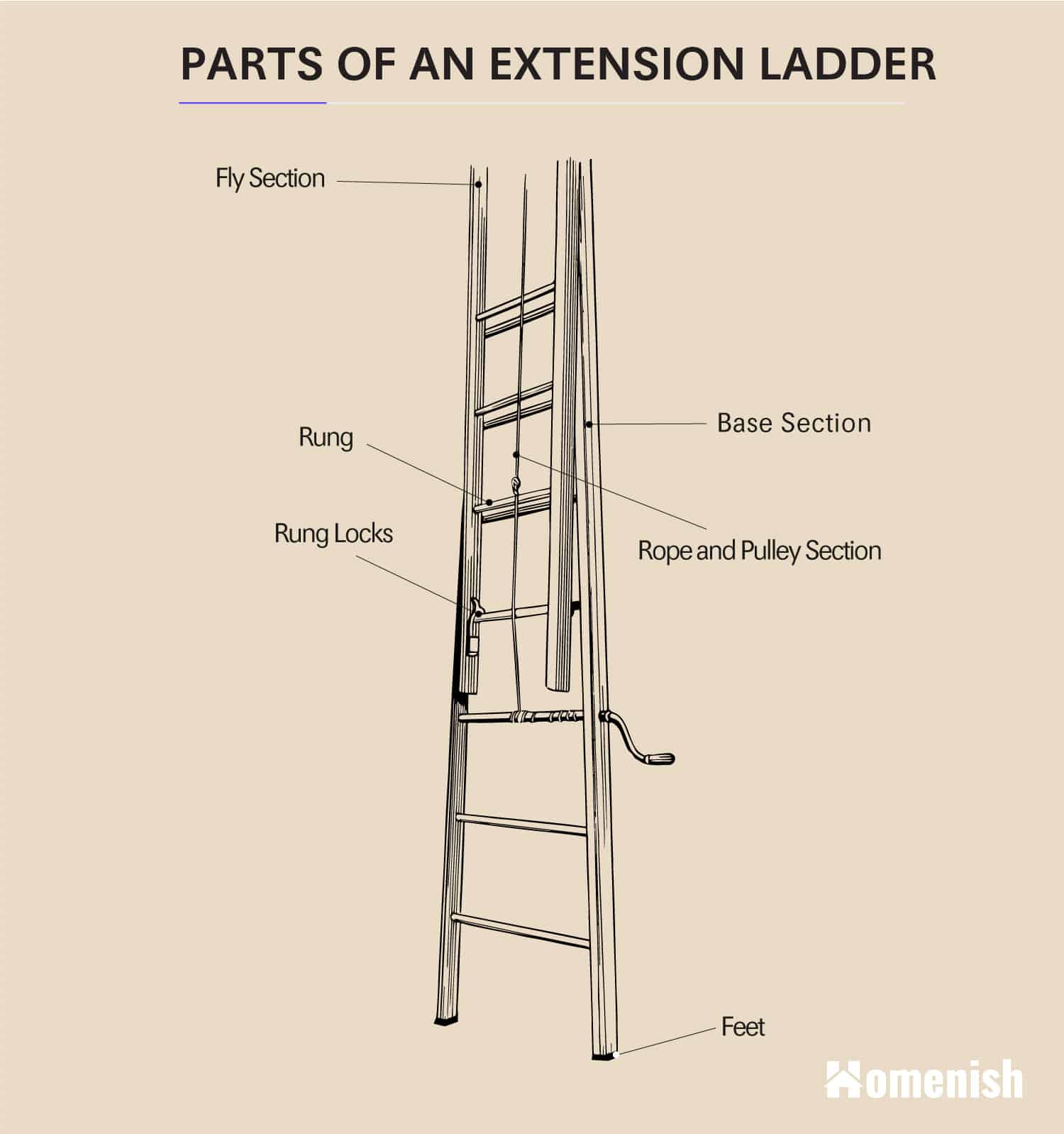
Parts of a Ladder (2 Diagrams For Step Ladder & Extension Ladder
![[DIAGRAM] Drawing Ladder Diagram](https://www.homestratosphere.com/wp-content/uploads/2018/02/03_Extension-Ladder.jpg)
[DIAGRAM] Drawing Ladder Diagram
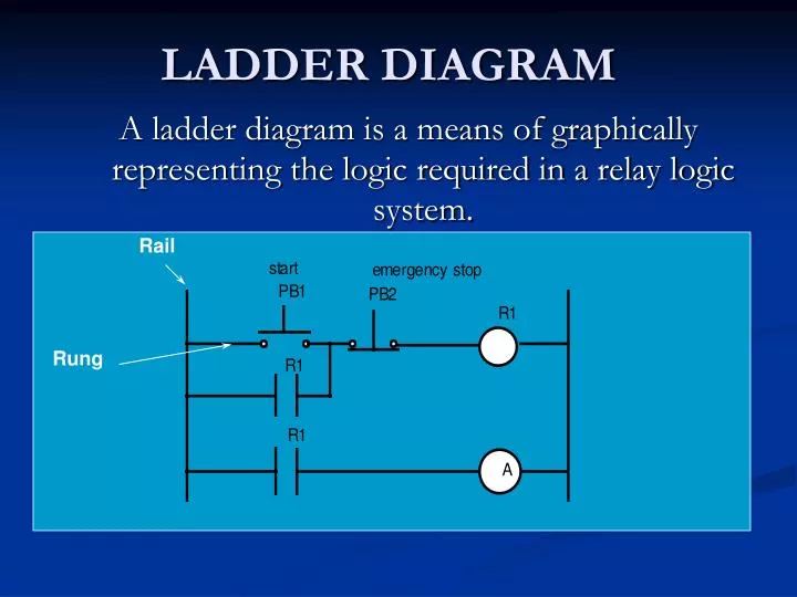
PPT LADDER DIAGRAM PowerPoint Presentation, free download ID2148345
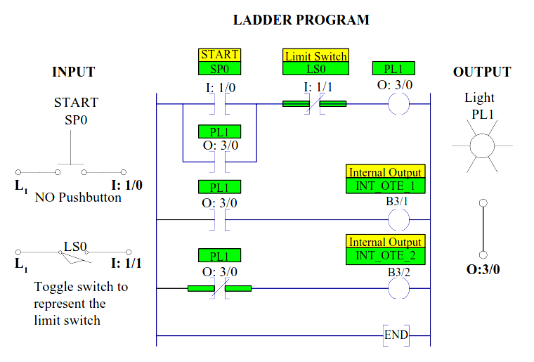
A Simple Ladder Diagram with NO and NC Contacts
Web Ladder Logic (Also Known As Ladder Diagram Or Ld) Is A Programming Language Used To Program A Plc (Programmable Logic Controller).
Ladder Logic Symbols Represent Various Components And Operations In A Control System, Such As Inputs, Outputs, Logical Operations, Timers, Counters, And More.
Web Basics Of Ladder Logic Symbols.
They Are Called “Ladder” Diagrams Because They Resemble A Ladder, With Two Vertical Rails (Supply Power) And As Many “Rungs” (Horizontal Lines) As There Are Control Circuits To Represent.
Related Post: