Valve Drawing
Valve Drawing - Draw a length of pipe in the bw size range. Generate 2d and 3d cad models for your pneumatic. Web in this article, we will delve into the importance of valve design, explore different types of valves, highlight advancements in valve technology, discuss valve sizing and selection,. For use by consulting engineers in the preparation of layouts and plan details. We build, test & ship your actuated valve assemblies the same day. Web move a disc, or plug into or against an orifice (for example, globe or needle type valve). The symbol typically consists of the actual valve symbol, and. Web a piping and instrumentation diagram (p&id) is a graphic representation of a process system that includes the piping, vessels, control valves, instrumentation, and other. Web isometric drawing symbols for piping valves. A valve controls system or process fluid flow and pressure by performing. We have a vast range of experience and depth of expertise in 2d drafting and 3d modeling of. A valve controls system or process fluid flow and pressure by performing. Web in each process and instrumentation diagram, valves have specific symbols that make them easy to recognize. To read and understand engineering fluid diagrams and prints, usually referred to as. Generic symbols will tell you that there is a valve in the line, but they will not. Draw a length of pipe in the bw size range. Following are the main types of valves: Generate 2d and 3d cad models for your pneumatic. Free shipping orders over $99. This diagram comprises various components, including control valves,. Web a piping and instrumentation diagram is a detailed graphical representation of an industrial process plant. Web a valve is a mechanical device that controls the flow of fluid and pressure within a system or process. We build, test & ship your actuated valve assemblies the same day. Following are the main. To read and understand engineering fluid diagrams and prints, usually referred to as p&ids, an. This diagram comprises various components, including control valves,. Some of the most commonly used pieces of process equipment that show up on p&ids are valves. Draw a length of pipe in the bw size range. Free shipping orders over $99. Generic symbols will tell you that there is a valve in the line, but they will not. Web a valve is a mechanical device that controls the flow of fluid and pressure within a system or process. Web in each process and instrumentation diagram, valves have specific symbols that make them easy to recognize. Wafer butterfly valve drawings are used. Draw a length of pipe in the bw size range. Web we have been in business for over 25 years serving the valve control industry. We build, test & ship your actuated valve assemblies the same day. This diagram comprises various components, including control valves,. Web a piping and instrumentation diagram (p&id) is a graphic representation of a process system. To read and understand engineering fluid diagrams and prints, usually referred to as p&ids, an. Valve symbols are used to. This document describes how to draw valves using spoolfab. Web move a disc, or plug into or against an orifice (for example, globe or needle type valve). We have a vast range of experience and depth of expertise in 2d. We have a vast range of experience and depth of expertise in 2d drafting and 3d modeling of. Web to provide 2d drawings of valves, etc. The symbol typically consists of the actual valve symbol, and. Some of the most commonly used pieces of process equipment that show up on p&ids are valves. 2d drawings are saved as an. Web a piping and instrumentation diagram (p&id) is a graphic representation of a process system that includes the piping, vessels, control valves, instrumentation, and other. Wafer butterfly valve drawings are used to provide detailed information about the design of a particular butterfly valve, including pressure. We build, test & ship your actuated valve assemblies the same day. Web a valve. Slide a flat, cylindrical, or spherical surface across an orifice (for example, gate and plug. Following are the main types of valves: Free shipping orders over $99. Web to provide 2d drawings of valves, etc. Web there are two types of valve symbols — first, generic symbols, and second, a symbol with a modifier. Generate 2d and 3d cad models for your pneumatic. A valve controls system or process fluid flow and pressure by performing. Valve symbols are used to. Web a piping and instrumentation diagram is a detailed graphical representation of an industrial process plant. This document describes how to draw valves using spoolfab. Web a piping and instrumentation diagram (p&id) is a graphic representation of a process system that includes the piping, vessels, control valves, instrumentation, and other. For use by consulting engineers in the preparation of layouts and plan details. Web a valve is a mechanical device that controls the flow of fluid and pressure within a system or process. Following are the main types of valves: Some of the most commonly used pieces of process equipment that show up on p&ids are valves. This article offers a comprehensive assortment of widely utilized p&id symbols for pipes, fittings, valves, strainers, and. Web the complex world of process and instrumentation drawings (p&ids) is replete with a range of valve diagrams and symbols. Web view technical drawings of our various valves here. This diagram comprises various components, including control valves,. Web there are two types of valve symbols — first, generic symbols, and second, a symbol with a modifier. Click on an open end to bring up the.
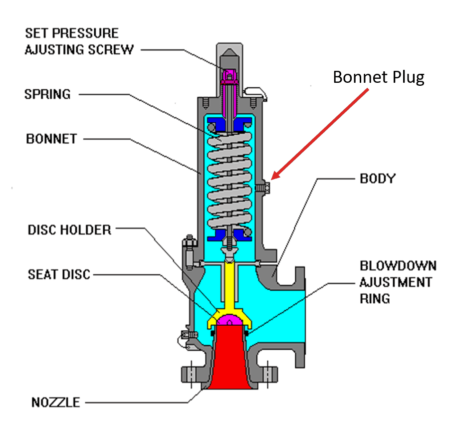
Pressure Relief Valve Learn about Safety Valve and Vacuum Relief Valve
![Gate Valve 3D Model DWG [ Drawing Free ] in AutoCAD for Architect.](https://dwgfree.com/wp-content/uploads/2021/02/Gate-Valve-3D-dwg-in-autocad-drawing.jpg)
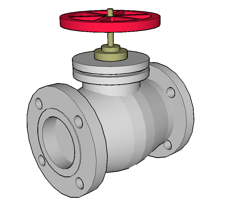
Gate Valve 3D Model DWG [ Drawing Free ] in AutoCAD for Architect.

Valves Manual Valves Ball, Rotary and Piston Valves CTG Technical

Full Welded Body Ball Valve Dynamic Drawing 2 Production Valves

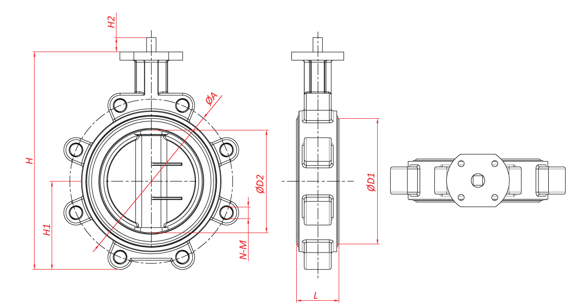
Understanding the Basics of Downloading a Butterfly Valve Drawing

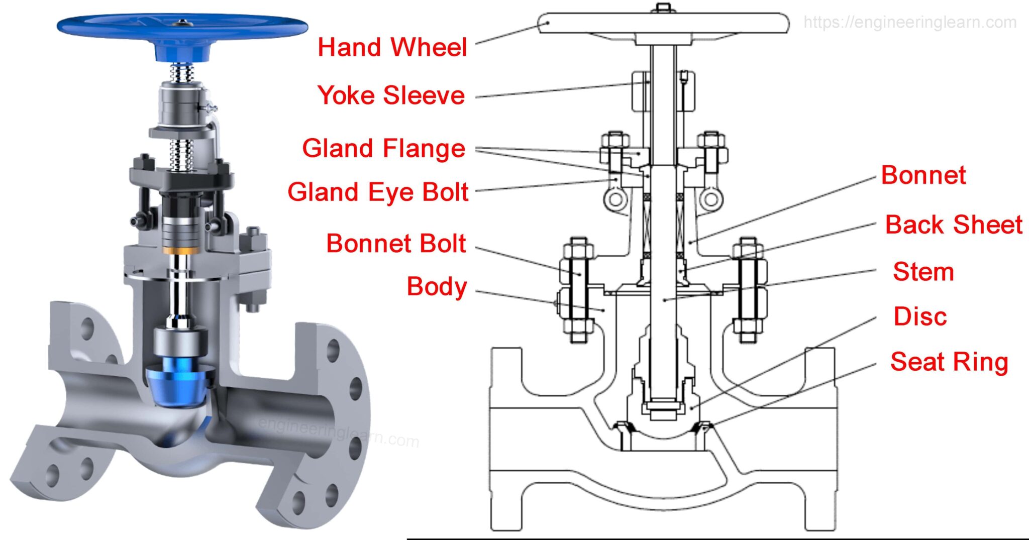
FileGlobe valve diagramen.svg Wikipedia

Gate valve detail 3d model sketchup file Cadbull

Flow Control Valve Definition, Types, Components & Working Principle

Technical drawing of a Rising Stem Gate Valve OSandY Gate valve

Types of Valves and Their Applications and Selection Criteria
Draw A Length Of Pipe In The Bw Size Range.
The Symbol Typically Consists Of The Actual Valve Symbol, And.
Generic Symbols Will Tell You That There Is A Valve In The Line, But They Will Not.
Web In This Article, We Will Delve Into The Importance Of Valve Design, Explore Different Types Of Valves, Highlight Advancements In Valve Technology, Discuss Valve Sizing And Selection,.
Related Post: