Trunnion Support Drawing
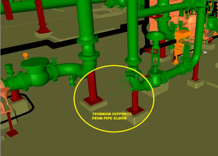
Trunnion Support Drawing - Installation guide for special pipe support. 3.1.2 for carbon steel and ferrous pipe materials through 9%. Parent pipe material to get stress values. Knowledge is nothing unless it is shared They are generally used in pairs, set apart at 180°. The inputs that will be required for pipe trunnion calculation are: An 8 dummy leg or base support doesn't mean use 8 pipe, it means the supported line is 8 and any parts that make up the support (pipe, wide flange, threaded rod, etc.) must be looked up on the standard drawing. As per the kellogg manual, all attachments to the pipe such as trunnion and lugs shall be designed such that the pipe shell bending and pressure stresses do not exceed the allowable. Horizontal trunnion support on vertical pipework. Web normally this trunnion diameter is to be determined in the pipe stress analysis with the drawing guidance. There are relevant case studies of trunnion failures and inspection, provided by hois members, to increase awareness and understanding of the challenges associated with trunnion inspection. Web trunnions on iso’s would “normally†be depicted in a very simple graphic symbol. Web how to read trunnion or dummy pipe support whats is a dummy pipe support what is trunnion pipe support. Knowledge is nothing unless it is shared Use this support on pump suctlon and discharge line. Web types of piping support that not defined by a standard combination of supports and are designed to meet the piping requirements are called special pipe supports. An 8 dummy leg or base support doesn't mean use 8 pipe, it means the supported line. Horizontal trunnion support on vertical pipework. 501 piping design 502 pipe, fittings and valves 525 painting and coating. The inputs that will be required for pipe trunnion calculation are: Web support trunnions are provided with reinforcement when specified by piping stress engineers. Web this document contains an overview of trunnion design, geometry and degradation mechanisms. Horizontal trunnion support on vertical pipework. There are relevant case studies of trunnion failures and inspection, provided by hois members, to increase awareness and understanding of the challenges associated with trunnion inspection. Knowledge is nothing unless it is shared Web for example we specify all supports by the size of the supported line and provide a standard reference drawing number;. Their axis is perpendicular to a line drawn from the center of the column to the center of the pipe at the location of support. When generate the isometric, single and double trunnion. Pipe trunnion od and thickness. The inputs that will be required for pipe trunnion calculation are: They are generally used in pairs, set apart at 180°. Knowledge is nothing unless it is shared The main goal for an iso drawing is to locate where this trunnion occurs on the piping spool. Horizontal trunnion support on vertical pipework. Web trunnions on iso’s would “normally†be depicted in a very simple graphic symbol. Web for example we specify all supports by the size of the supported line and. Pipe trunnion od and thickness. How to change the isometric symbol of single & double trunnion support for isometric drawing in openplant isometric manager connect edition. An isometric drawing covers a complete line as per the line list and p&id. Web supports welded to piping. Parent pipe material to get stress values. Pipe supports detailed in the attached drawings shall be used for all gsepn projects. When generate isometric, dummy leg and trunnion support symbol shows as pipe. It shows all information necessary for fabrication and erection. There are relevant case studies of trunnion failures and inspection, provided by hois members, to increase awareness and understanding of the challenges associated with trunnion. Web supports welded to piping. Horizontal trunnions welded to the pipe take the vertical load of the pipe. Pipe trunnion od and thickness. Same as run pipe material or eq. An isometric drawing covers a complete line as per the line list and p&id. Web this document contains an overview of trunnion design, geometry and degradation mechanisms. The main goal for an iso drawing is to locate where this trunnion occurs on the piping spool. The inputs that will be required for pipe trunnion calculation are: It shows all information necessary for fabrication and erection. Pipe support loads from stress analysis software. How to use isometric custom symbol for dummy leg/ trunnion support & how to include them under support section of bill of material. Web trunnions on iso’s would “normally†be depicted in a very simple graphic symbol. Web support trunnions are provided with reinforcement when specified by piping stress engineers. Pipe supports detailed in the attached drawings shall be used for all gsepn projects. The dummy support calculation is based on m.w.kellogg design manual. They are generally used in pairs, set apart at 180°. Parent pipe material to get stress values. The designer should note that some supports require. As per the kellogg manual, all attachments to the pipe such as trunnion and lugs shall be designed such that the pipe shell bending and pressure stresses do not exceed the allowable. This has been shown with the context with autoplant modeler and openplant isometric manager. Web supports welded to piping. The main goal for an iso drawing is to locate where this trunnion occurs on the piping spool. Web this document contains an overview of trunnion design, geometry and degradation mechanisms. Web for example we specify all supports by the size of the supported line and provide a standard reference drawing number; Api 5l gr.b or eq. Web i have seen a standard trunnion/dummy support drawing for 3d bend but not for 5d bend.
What Is a Trunnion Support in Piping?

How to use Isometric Custom Symbol for Dummy Leg /Trunnion Support
Material Design Analysis of a Trunnion TurboFuture
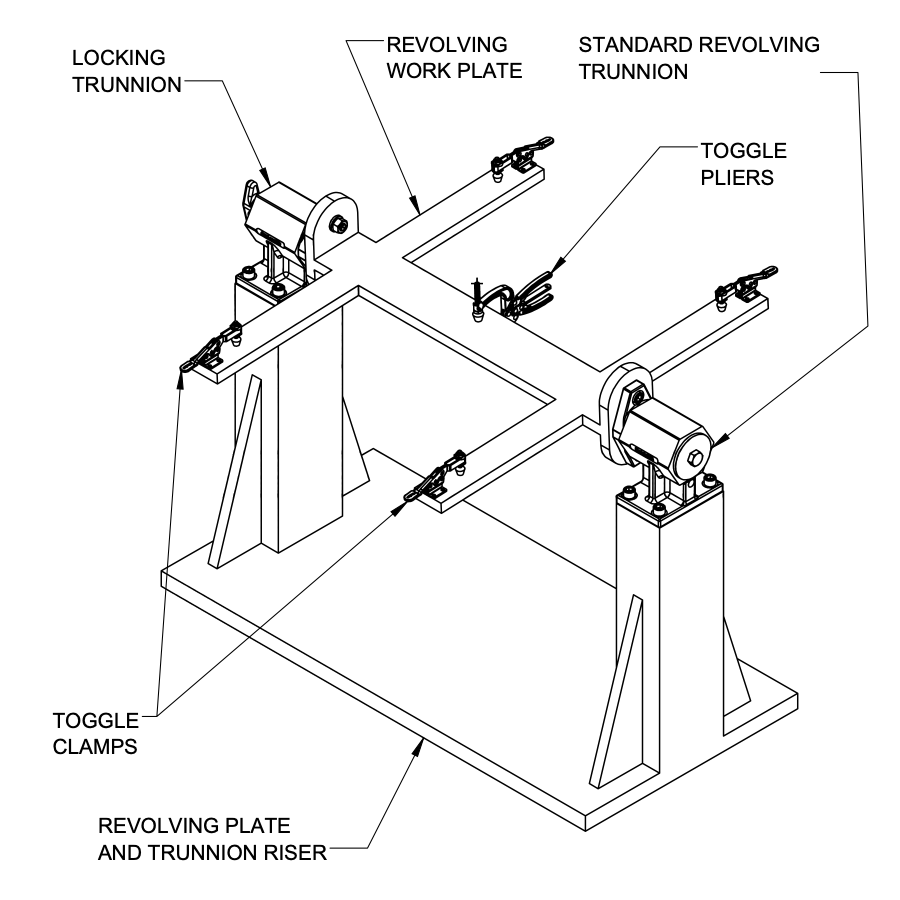
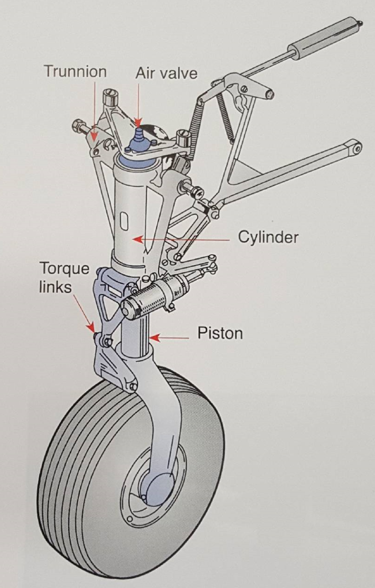
What are Trunnions? Carr Lane Mfg.
 copy.png)
What are Trunnions? Carr Lane Mfg.

Dummy Support Center Formula & Trunnion Support Center Formula/Dummy
Pipe Trunnion or Dummy Support and Their Stress Calculation (PDF

Pipe Trunnion or Dummy Support and Their Stress Calculation (PDF

Dummy Support Bottom formula/Trunnion Support For Elbow Formula/Dummy

Trunnion (Dummy) Support Stress Online Calculation
For Special Pipe Supports A Fully Detailed Support Fabrication Drawing Is Produced.
The Use Of Pipe Supports Marked As ‘Not Preferred’ Shall Be Avoided If At All Possible.
Line List (Process) Latest P&Id/Pefs (Process) (Issued Signed Copy) General Information About Piping Isometric Drawings.
Pipe Support Loads From Stress Analysis Software.
Related Post: