Tech Drawing Symbols
Tech Drawing Symbols - Toray maintains a network of research and development centers around the world. What are the types of technical drawings? At environment & mobility development center in japan, automotive center europe in germany and automotive center china, we collaborate closely with manufacturers, drawing on research and engineering expertise from across the toray group to develop. Most symbols have been in y14.5 since at least 1994. Essential for designers, draftsmen, cad users, engineers, technicians, inspection and workshop professionals, engineering students, hobbyists and inventors. Data and information in drawings. Web 2022 graduate program information. In this article, we’ll introduce how does gd&t works, the gd&t terms and definitions, as well as the chart of gd&t symbols. Web what are the most commonly used engineering drawing symbols and their meanings? They can also be used after the fact. Web engineering drawing abbreviations and symbols are used to communicate and detail the characteristics of an engineering drawing. Engineering drawings are technical diagrams and representations meant to define parameters and other plans for something that is to be engineered. Work with runsom for your cnc programming projects. Abz stays true to the mission and sets sail from the heart. First,. You can also check out the gd&t symbols and terms on our site. This article provides an overview of technical drawings. It, in the form of a large m agnet, symbolizes the powe rful attraction of the lujiazui finance and trade zone, drawing talent and information from around the world to shanghai. Web engineering drawing abbreviations and symbols are used. Web this list includes abbreviations common to the vocabulary of people who work with engineering drawings in the manufacture and inspection of parts and assemblies. Need to know for dispelling uncertainty in drawings. Work with runsom for your cnc programming projects. Common engineering drawing abbreviations used in cnc machining. Data and information in drawings. Click any technical drawing example below to start working on it now. Technical drawings, also called mechanical drawings, mechanical working drawings or manufacturing drawings, provide the details needed to manufacture the product being depicted. What are the types of technical drawings? Strives to become one of the most advanced enterprises of cable machinery. Web to use technical drawings effectively, specialist. Web once you know what type of drawing you're looking at, take some time to familiarize yourself with the common symbols used in technical drawings. Web basic types of symbols used in engineering drawings are countersink, counterbore, spotface, depth, radius, and diameter. Web engineering drawing abbreviations and symbols are used to communicate and detail the characteristics of an engineering drawing.. This article provides an overview of technical drawings. The table shows dimensioning symbols found on drawings. Web engineering drawing abbreviations and symbols are used to communicate and detail the characteristics of an engineering drawing. Web an engineering (or technical) drawing is a graphical representation of a part, assembly, system, or structure and it can be produced using freehand, mechanical tools,. Working drawings are the set of technical drawings used during the manufacturing phase of a product. Why abbreviations and symbols are needed for engineering drawing? What are the types of technical drawings? Note the comparison with the iso standards. Technical drawing and design is a crucial means of communication in the construction industry and how professionals in the field visually. Work with runsom for your cnc programming projects. Note the comparison with the iso standards. Web to use technical drawings effectively, specialist knowledge is required to understand the symbols, rules, and standards used. Strives to become one of the most advanced enterprises of cable machinery. Web basic types of symbols used in engineering drawings are countersink, counterbore, spotface, depth, radius,. Web identifying symbols and notations: Web creating or interpreting technical drawings throughout the world. Toray maintains a network of research and development centers around the world. In this article, we’ll introduce how does gd&t works, the gd&t terms and definitions, as well as the chart of gd&t symbols. This article provides an overview of technical drawings. Here are more commonly used engineering drawing symbols and design elements as below. What is a technical drawing? Web basic types of symbols used in engineering drawings are countersink, counterbore, spotface, depth, radius, and diameter. The background of abz establishment is based on common dream and rich experience of wire and cable industry. Here is a gd&t symbols chart including. Engineering drawing symbols play a vital role in communication among engineers and other stakeholders involved in the design and construction process. Technical drawings, also called mechanical drawings, mechanical working drawings or manufacturing drawings, provide the details needed to manufacture the product being depicted. Data and information in drawings. Web basic types of symbols used in engineering drawings are countersink, counterbore, spotface, depth, radius, and diameter. Web this list includes abbreviations common to the vocabulary of people who work with engineering drawings in the manufacture and inspection of parts and assemblies. Common engineering drawing abbreviations used in cnc machining. Working drawings are the set of technical drawings used during the manufacturing phase of a product. Web how to read an engineering drawing symbol. Work with runsom for your cnc programming projects. Why abbreviations and symbols are needed for engineering drawing? The background of abz establishment is based on common dream and rich experience of wire and cable industry. Web drafting symbols reference sheet: Most symbols have been in y14.5 since at least 1994. This article provides an overview of technical drawings. We offer you our tips which we believe are useful for dispelling uncertainty by comparing the symbol with its graphic representation. These symbols usually represent measurements, dimensions, angles, and other specifications related to the object being drawn.
Machining Drawing Symbols Chart A Visual Reference of Charts Chart

Mechanical Drawing Symbols Technical Drawing Software Mechanical

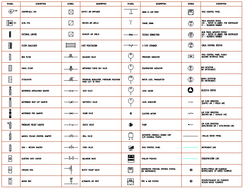
Blueprint Symbolsblueprint Symbols Hvac Design

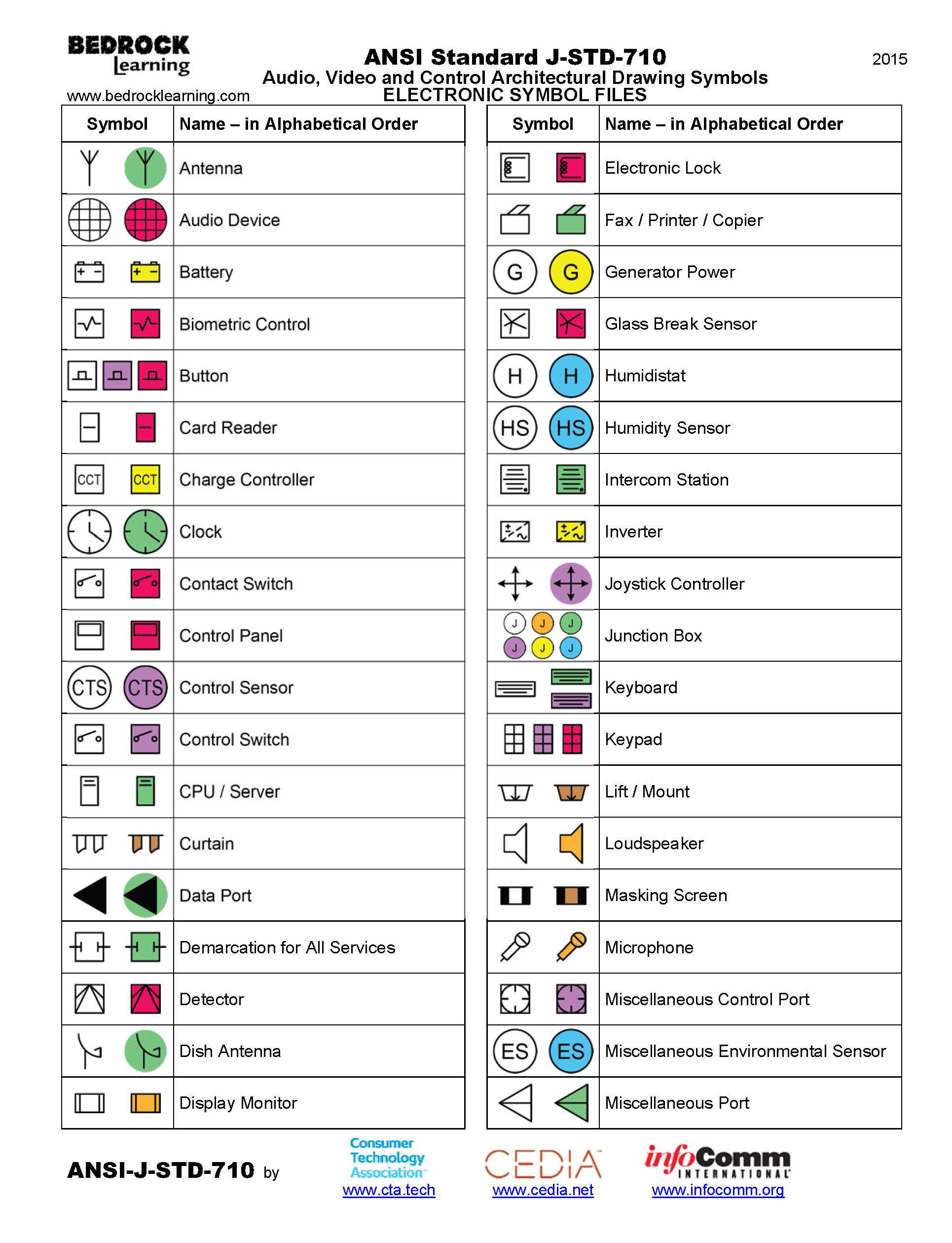
ANSI Standard JSTD710 Architectural Drawing Symbols Bedrock Learning

Mechanical Engineering Technical Drawing Symbols

Engineering Drawing Symbols And Their Meanings Pdf at PaintingValley

Engineering Drawing Symbols And Their Meanings Pdf at PaintingValley

Technical Drawing Symbols And Their Meanings Design Talk

Engineering Drawing Symbols And Their Meanings Pdf at PaintingValley

Mechanical Engineering Drawing Symbols Pdf Free Download at
The Following Is A Short List Of Symbols That Normally Appear On A Technical Drawing And Need Understanding.
Web Once You Know What Type Of Drawing You're Looking At, Take Some Time To Familiarize Yourself With The Common Symbols Used In Technical Drawings.
They Can Also Be Used After The Fact.
Web Add Your Information, Drag And Drop Technical Symbols And Smartdraw Will Help You Align And Connect Them.
Related Post: