Symbols For Electrical Drawings
Symbols For Electrical Drawings - These symbols are largely standardized internationally today, but may vary from country to country. Web electrical symbols used today in wiring and ladder diagrams come from national electrical manufacturer association (nema) or the international electrical coalition (iec). The organization standardized the electrical symbols to make drawings simpler to read and easier to communicate. Understanding electrical symbols is a foundational aspect of architectural design and planning. Web electrical circuit diagram symbols. Electrical wiring symbols, meanings and drawings of all electrical symbols and their function. Electrical plan symbols used in electrical drawings, including power, lighting, security, fire alarm, and communications symbols. These symbols represent components in schematic diagrams. In circuit diagrams, graphical symbols identify network components and devices. If you are a beginner in electronics and electrical plan, then the first thing you have to learn is schematic or circuit diagrams and the symbols used in them. The symbols represent electrical and electronic components. The two schematic symbols below show the different states of an spst switch. The organization standardized the electrical symbols to make drawings simpler to read and easier to communicate. For fluid systems, it is easy to think of going from a high pressure to a lower pressure. Amplifiers (denoted by triangle shapes) increase. A single line diagram may start out in the design development phase of a project as a basic. Represented by a zigzag line. An electronic symbol is a pictogram used to represent various electrical and electronic devices or functions, such as wires, batteries, resistors, and transistors, in a schematic diagram of an electrical or electronic circuit. Frequently occurring technical phrases. Web basic electrical symbols contain earth electrode, cell, battery, resistor, etc. Understanding electrical symbols is a foundational aspect of architectural design and planning. These icons serve as a standardized and universally recognized language that engineers, electricians, and technicians use to communicate and understand. Web electrical systems such as lights, switches, circuit breakers, distribution panels, and fixtures are denoted using various. Web electrical systems such as lights, switches, circuit breakers, distribution panels, and fixtures are denoted using various symbols described in legends. What are electrical and electronics symbols? Represented by a zigzag line. Web electrical circuit diagram symbols. Understanding electrical symbols is a foundational aspect of architectural design and planning. Understanding electrical symbols is a foundational aspect of architectural design and planning. Whether you are a novice or a professional engineer, these basic symbols can help create accurate electrical and circuit diagrams in minutes. A single line diagram may start out in the design development phase of a project as a basic. The basics of electrical symbols. Electrical symbols or. The organization standardized the electrical symbols to make drawings simpler to read and easier to communicate. Electrical symbols are the most commonly used symbols in circuit diagramming. Represented by a zigzag line. Amplifiers (denoted by triangle shapes) increase the output signal in your circuit. A spst (single pole, single throw) switch is an on and off switch. There are some standard symbols to represent the components in a circuits. Electrical symbols are the most commonly used symbols in circuit diagramming. Web for example, a breaker symbol is shown as follows: These symbols represent components in schematic diagrams. Whether you are a novice or a professional engineer, these basic symbols can help create accurate electrical and circuit diagrams. Electrical symbols are the most commonly used symbols in circuit diagramming. The basics of electrical symbols. The life of a single line diagram. Web for example, a breaker symbol is shown as follows: A spst (single pole, single throw) switch is an on and off switch. Amplifiers (denoted by triangle shapes) increase the output signal in your circuit. This is common with electrical schematics and is integral to understanding the drawings. Web electrical systems such as lights, switches, circuit breakers, distribution panels, and fixtures are denoted using various symbols described in legends. Web electrical symbols used today in wiring and ladder diagrams come from national electrical. Web spst switch es. There are some standard symbols to represent the components in a circuits. Web you will learn how to define the symbols that should be used according to the type of electrical diagram, clarify the choice of a symbol that should be used on a plan, specify why representation standards are used, and associate a type of. Electrical symbols or electronic circuits are virtually represented by circuit diagrams. Web importance of single line diagram. Web symbols (such as j, exp, cu) are used to indicate mathematical operations, chemical elements etc. The life of a single line diagram. This is common with electrical schematics and is integral to understanding the drawings. Electrical wiring symbols, meanings and drawings of all electrical symbols and their function. Web by santosh das | last updated on march 18, 2024. Electrical symbols are visual representations in electrical drawings and diagrams to convey information about components, devices, and connections within a circuit or system. Here is list of all the electrical wiring symbols, meanings and drawings for both residential and commercial. A spst (single pole, single throw) switch is an on and off switch. Web firstly, we have a selection of free electrical blueprint symbols in a dwg format available for download here. Amplifiers (denoted by triangle shapes) increase the output signal in your circuit. The top symbol indicates that the switch is in the off position, which blocks the path of current. These symbols provide a standardized way for engineers, electricians, and technicians to communicate and understand complex electrical circuits. Frequently occurring technical phrases are commonly rendered as abbreviations (such as e.m.f., p.d.). An electronic symbol is a pictogram used to represent various electrical and electronic devices or functions, such as wires, batteries, resistors, and transistors, in a schematic diagram of an electrical or electronic circuit.
Electrical Schematic Symbols CircuitsTune
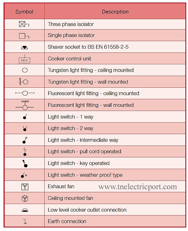
Why Electrical Symbols are important to Electricians?
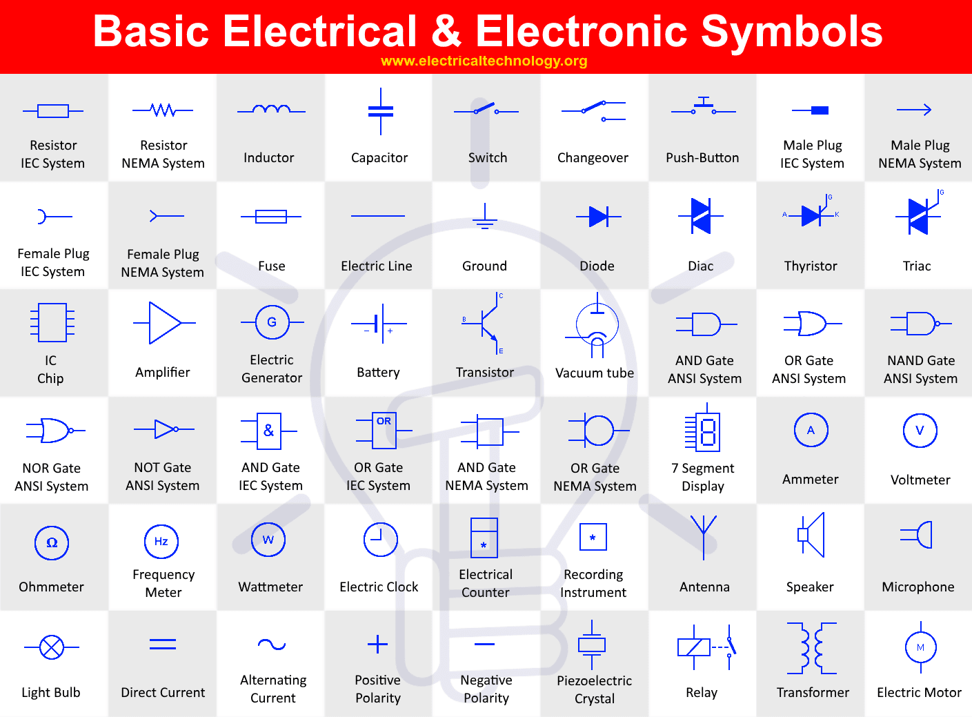
Basic & Important Electrical Symbols and Electronic Symbols

Electrical Symbols Electrical Drawing Symbols Electrical Academia
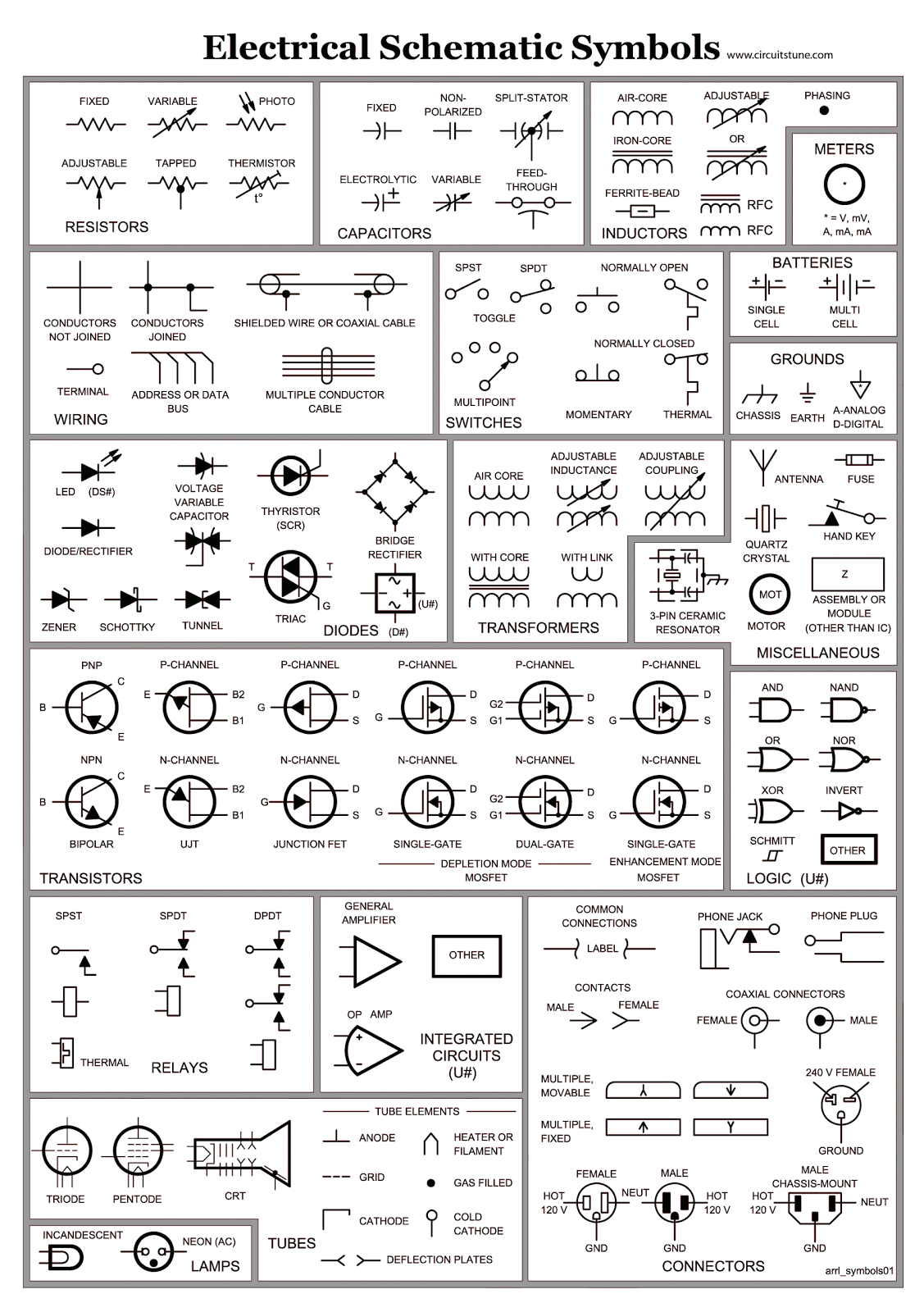
Electrical Schematic Symbols CircuitsTune
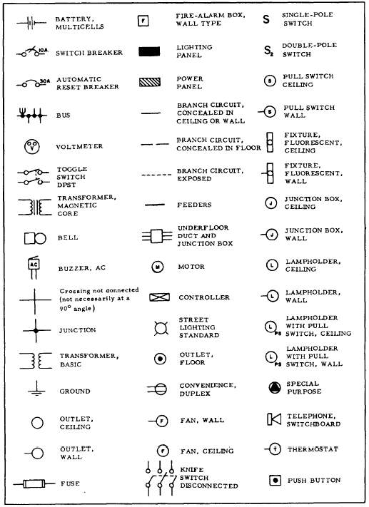
The electrical information and layouts in construction drawings
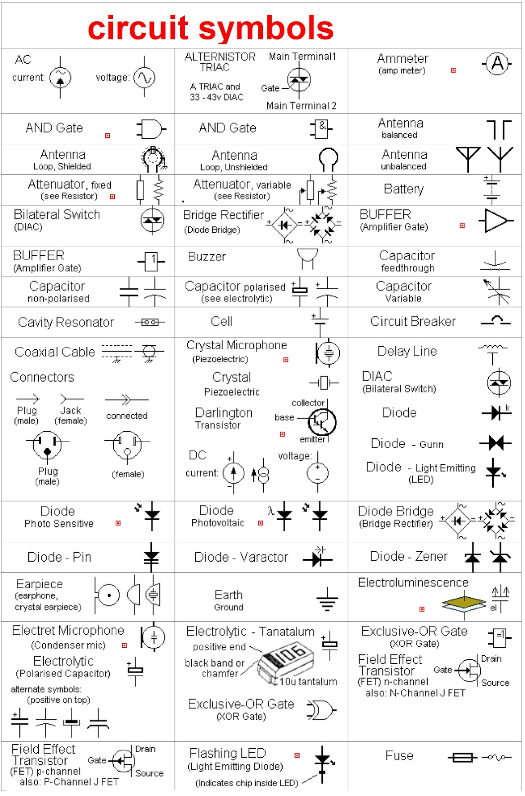
Symbols Used In Electrical Schematic Drawing
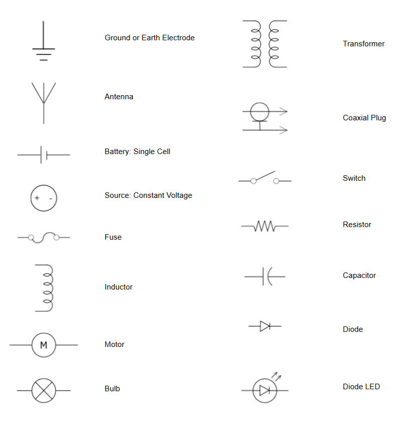
Electrical Symbols Try Our Electrical Symbol Software Free

Free CAD Blocks Electrical Symbols

Common Electrical Symbols Electrical symbols, Blueprint symbols, Dc
Understanding Electrical Symbols Is A Foundational Aspect Of Architectural Design And Planning.
Electrical Circuit Diagram Symbols Are Graphic Representations Of Electrical Components And Their Connections In A Circuit.
Capacitors (Parallel Lines) Store Energy In Your System, While Resistors (Zigzag Lines) Reduce Current Flow.
Web Spst Switch Es.
Related Post: