Pneumatic Drawing Symbols
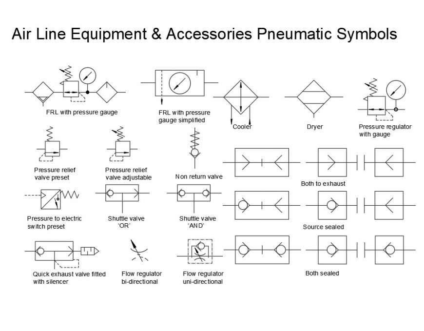
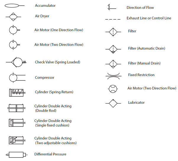
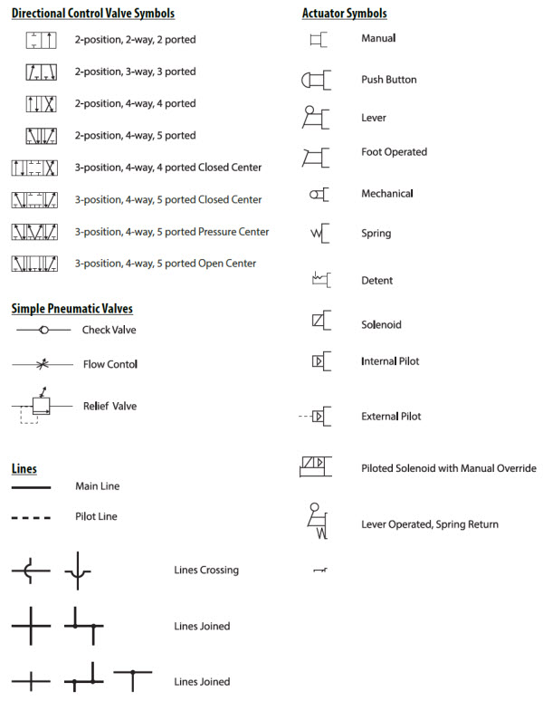
Pneumatic Drawing Symbols - The symbols used in the diagram. Jic / nfpa sample drawing; Web learn how to interpret pneumatic diagrams with symbols of directional control valves, line symbols, common equipment and actuator symbols. Web it is desired to move a 200lb load 12 inches at a rate of 20 cycles per minute. Web all the symbols you need to design your pneumatic circuit in.dxf format. Web for additional information on pneumatic and hydraulic schematics click on the following links: Web a detailed view of pneumatic circuit symbols and their meaning. With the new online release, it is easier than ever to draw your circuits. These symbols are fully explained in the usa. Outline of pneumatic circuit diagram creation program. Web a pneumatic circuit diagram can be easily created by using the database for pneumatic equipment drawing symbols. Valve symbols including solenoid valve symbols are those that are in common use. Symbols show the methods of actuation, the number of positions, the flow paths and the number of ports. Scan through and easily download the one you need. Jic /. Take a look at our comprehensive list of common symbols for use in circuit diagrams, available to download in pdf format. Beside pneumatic symbols the tool. Web all the symbols you need to design your pneumatic circuit in.dxf format. Web compressed air schematic symbols play a crucial role in understanding and designing pneumatic systems. The symbols used in the diagram. Web learn how to interpret pneumatic diagrams with symbols of directional control valves, line symbols, common equipment and actuator symbols. See examples of these symbols. Take a look at our comprehensive list of common symbols for use in circuit diagrams, available to download in pdf format. With the new online release, it is easier than ever to draw your circuits.. Valve symbols including solenoid valve symbols are those that are in common use. Web pneudraw allows you to draw pneumatic circuits quickly and easily. Using a 2” bore cylinder, about 64 psi is required to move the load. Take a look at our comprehensive list of common symbols for use in circuit diagrams, available to download in pdf format. Here. Outline of pneumatic circuit diagram creation program. Beside pneumatic symbols the tool. It contains a wide range of standard circuit diagram symbols as well as all components from the. At pneumatics & sensors ireland, we find that clients are sometimes unsure of the meaning of pneumatic symbols on some of their machinery. Web for additional information on pneumatic and hydraulic. Web types of symbols commonly used in drawing circuit diagrams for fluid power systems are pictorial, cutaway, and graphic. Web the schematic diagram typically consists of symbols representing various components and lines indicating the flow of compressed air or gas. With the new online release, it is easier than ever to draw your circuits. Using a 2” bore cylinder, about. Scan through and easily download the one you need. Web a pneumatic circuit diagram can be easily created by using the database for pneumatic equipment drawing symbols. Web all the symbols you need to design your pneumatic circuit in.dxf format. Web the schematic diagram typically consists of symbols representing various components and lines indicating the flow of compressed air or. With the new online release, it is easier than ever to draw your circuits. These symbols provide a standardized representation of various. Web the schematic diagram typically consists of symbols representing various components and lines indicating the flow of compressed air or gas. Jic / nfpa sample drawing; It contains a wide range of standard circuit diagram symbols as well. Scan through and easily download the one you need. Volume symbol description circuit symbols are used through this catalogue and on the labels of most smc pneumatic products. These symbols provide a standardized representation of various. Adding 25% gives an operating. Web a pneumatic circuit diagram can be easily created by using the database for pneumatic equipment drawing symbols. It contains a wide range of standard circuit diagram symbols as well as all components from the. Take a look at our comprehensive list of common symbols for use in circuit diagrams, available to download in pdf format. Jic / nfpa sample drawing; Beside pneumatic symbols the tool. Web graphic symbols for pneumatic equipment. Beside pneumatic symbols the tool. Jic / nfpa sample drawing; It contains a wide range of standard circuit diagram symbols as well as all components from the. Using a 2” bore cylinder, about 64 psi is required to move the load. Web compressed air schematic symbols play a crucial role in understanding and designing pneumatic systems. Valve symbols including solenoid valve symbols are those that are in common use. Web all the symbols you need to design your pneumatic circuit in.dxf format. Here is a brief breakdown of how to read a symbol. Web pneudraw allows you to draw pneumatic circuits quickly and easily. Web for additional information on pneumatic and hydraulic schematics click on the following links: Web it is desired to move a 200lb load 12 inches at a rate of 20 cycles per minute. Outline of pneumatic circuit diagram creation program. Symbols show the methods of actuation, the number of positions, the flow paths and the number of ports. Volume symbol description circuit symbols are used through this catalogue and on the labels of most smc pneumatic products. Adding 25% gives an operating. Web symbols used in pneumatic air supply and distribution are designed to illustrate the function of valves and other necessary devices in the system.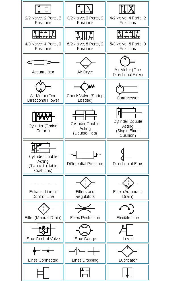
Pneumatics Banff Academy Technological Studies 07
Pneumatic Symbols Chart With Meanings

Valve Operator Pneumatic Symbols CAD Block And Typical Drawing For
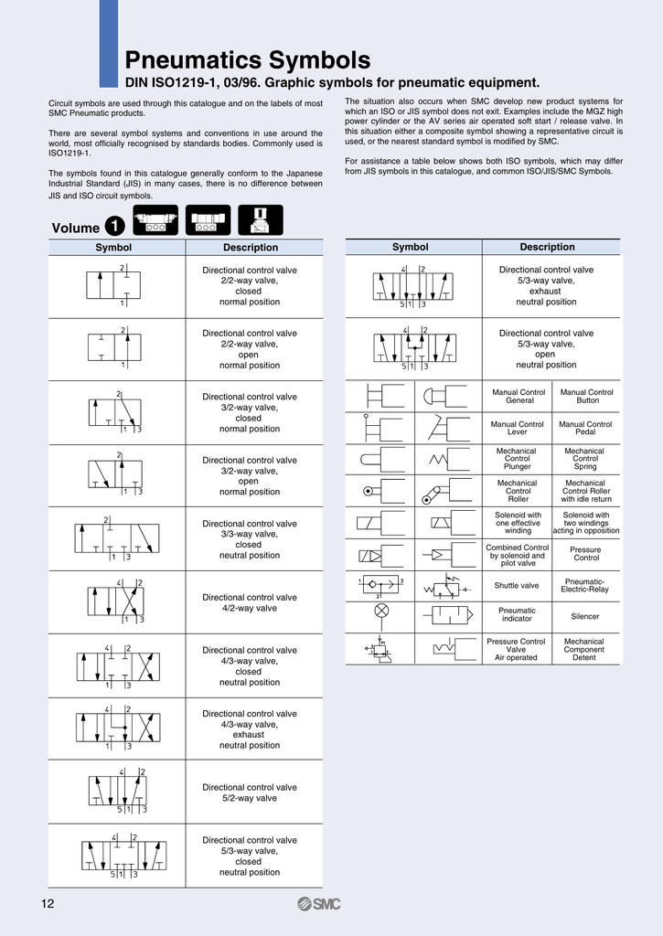
Pneumatics Symbols

Pneumatic Schematic Symbols Autocad
Common Symbols Used in Pneumatic Systems and Instrumentations
Pneumatic Circuit Symbols Explained Library.AutomationDirect

Actuator Pneumatic Symbols CAD Block And Typical Drawing

Pneumatic Symbols explained Pneumatics & Sensors Ireland

Pneumatic Symbols explained Pneumatics & Sensors Ireland
Web Types Of Symbols Commonly Used In Drawing Circuit Diagrams For Fluid Power Systems Are Pictorial, Cutaway, And Graphic.
Web The Schematic Diagram Typically Consists Of Symbols Representing Various Components And Lines Indicating The Flow Of Compressed Air Or Gas.
At Pneumatics & Sensors Ireland, We Find That Clients Are Sometimes Unsure Of The Meaning Of Pneumatic Symbols On Some Of Their Machinery.
These Symbols Provide A Standardized Representation Of Various.
Related Post: