Pipe Isometric Drawing
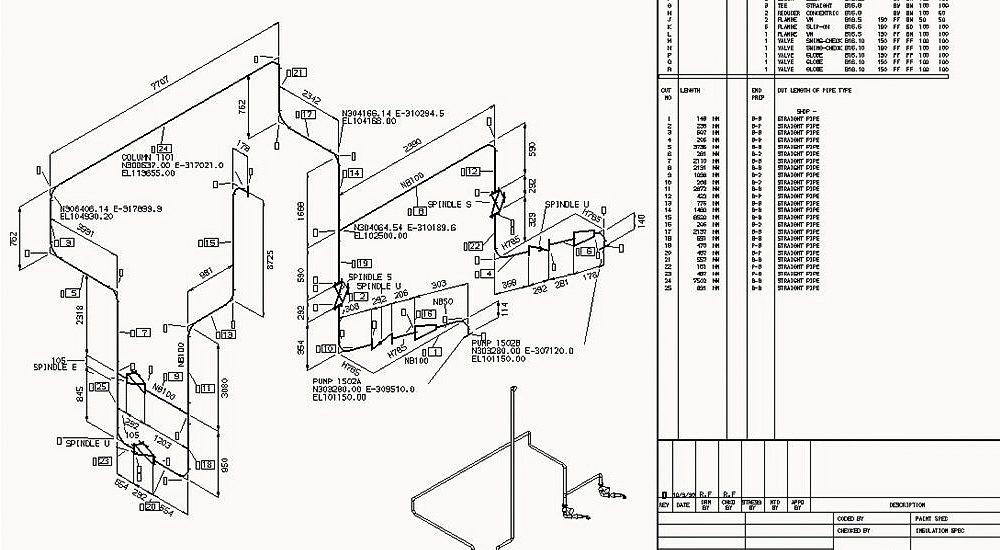
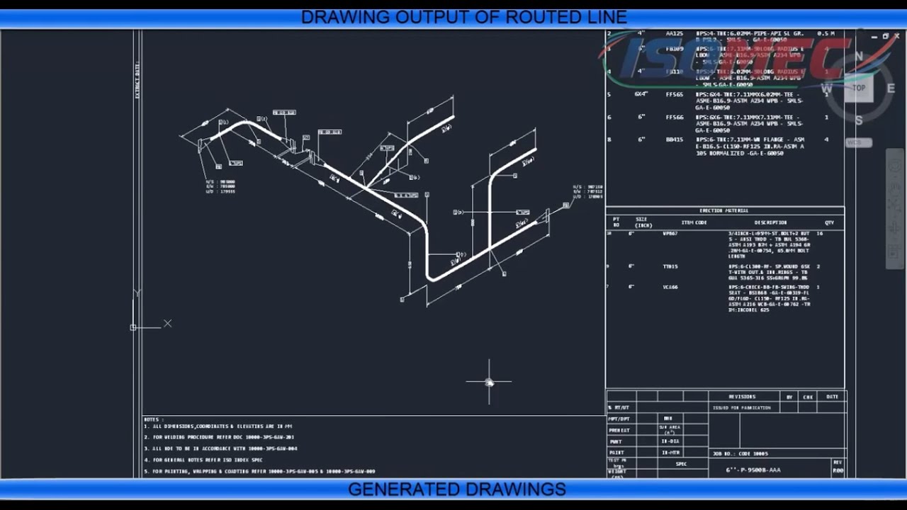
Pipe Isometric Drawing - Piping isometric drawings are detailed technical illustrations that show a 3d view of piping systems. How to read iso drawings. These drawings provide a detailed 3d illustration of a. Work from hand sketches or just draw them directly. Unlike orthographic drawings that show different views (front, side, and. Isometric drawings are typically used to. Web drawing piping isometrics : Web what are pipeline isometric drawings? Web the main body of a piping isometric drawing is consist of: Web the fitting, flange, and valve drawing symbols unique to isometrics are depicted. We are concluding our first pipefitter series run with a video on how to draw isometric drawings. Quickly produce installation isometrics and fabrication spool drawings. Open windows explorer and go to the isometric folder in your project. The piping isometrics life cycle. Web the fitting, flange, and valve drawing symbols unique to isometrics are depicted. Web isometrics are used as fabrication & shop drawings for pipe run fabrication. Work from hand sketches or just draw them directly. Web the main body of a piping isometric drawing is consist of: Web piping isometrics are generally produced from orthographic drawings and are important pieces of information to engineers. Web key features of isometric drawings. Web piping design is a critical discipline in mechanicaal engineering that involves the planning, layout, and specification of the systems used to transport fluids, gases, and other. Open windows explorer and go to the isometric folder in your project. Web go to skew > slopesymbols > ratio. Piping isometric drawings are detailed technical illustrations that show a 3d view of. Web pipeline isometric drawings are crucial visual representations in the fields of engineering and construction. Open windows explorer and go to the isometric folder in your project. Web pipeline isometrics are detailed drawings used in engineering and design to represent the 3d layout of a pipeline system on a 2d surface. Weld joint type and its location; Quickly produce installation. Managing piping isometrics with the isometric tracker. Isometric drawings are typically used to. Work from hand sketches or just draw them directly. Weld joint type and its location; Web piping design is a critical discipline in mechanicaal engineering that involves the planning, layout, and specification of the systems used to transport fluids, gases, and other. How to read iso drawings. Open windows explorer and go to the isometric folder in your project. These drawings provide a detailed 3d illustration of a. Web © 2024 google llc. Piping isometric drawings are detailed technical illustrations that show a 3d view of piping systems. The use of coordinate and elevation callouts to determine configuration dimensions of the routed. These drawings provide a detailed 3d illustration of a. Web how to read piping isometric drawing symbols. Web a piping isometric drawing is a technical illustration that presents a 3d representation of a piping system. Web isometrics are used as fabrication & shop drawings for pipe. Weld joint type and its location; Web pipeline isometric drawings are crucial visual representations in the fields of engineering and construction. Web a piping isometric drawing is a technical illustration that presents a 3d representation of a piping system. Check the annotation's block name. Quickly produce installation isometrics and fabrication spool drawings. These drawings provide a detailed 3d illustration of a. Weld joint type and its location; Web © 2024 google llc. Web drawing piping isometrics : Web the main body of a piping isometric drawing is consist of: Isometrics also provide a drafter with the ability to calculate angular offsets in the pipe run. Piping isometric drawings are detailed technical illustrations that show a 3d view of piping systems. Managing piping isometrics with the isometric tracker. Web isometrics are used as fabrication & shop drawings for pipe run fabrication. Unlike orthographic drawings that show different views (front, side,. Web © 2024 google llc. Unlike orthographic drawings that show different views (front, side, and. Isometric drawings are typically used to. Web pipeline isometrics are detailed drawings used in engineering and design to represent the 3d layout of a pipeline system on a 2d surface. In very complex or large piping systems, piping. Web drawing piping isometrics : Web go to skew > slopesymbols > ratio. Web piping isometrics are generally produced from orthographic drawings and are important pieces of information to engineers. Web piping design is a critical discipline in mechanicaal engineering that involves the planning, layout, and specification of the systems used to transport fluids, gases, and other. Managing piping isometrics with the isometric tracker. Web how to read piping isometric drawing symbols. Web the main body of a piping isometric drawing is consist of: Weld joint type and its location; Web what are pipeline isometric drawings? Isometrics also provide a drafter with the ability to calculate angular offsets in the pipe run. Web the fitting, flange, and valve drawing symbols unique to isometrics are depicted.
Learn isometric drawings (piping isometric)

How to Draw Isometric Pipe Drawings in Autocad Gautier Camonect
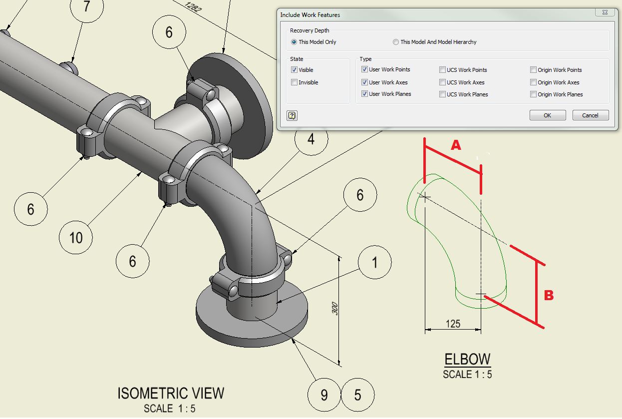
Piping Isometric Drawings Autodesk Community
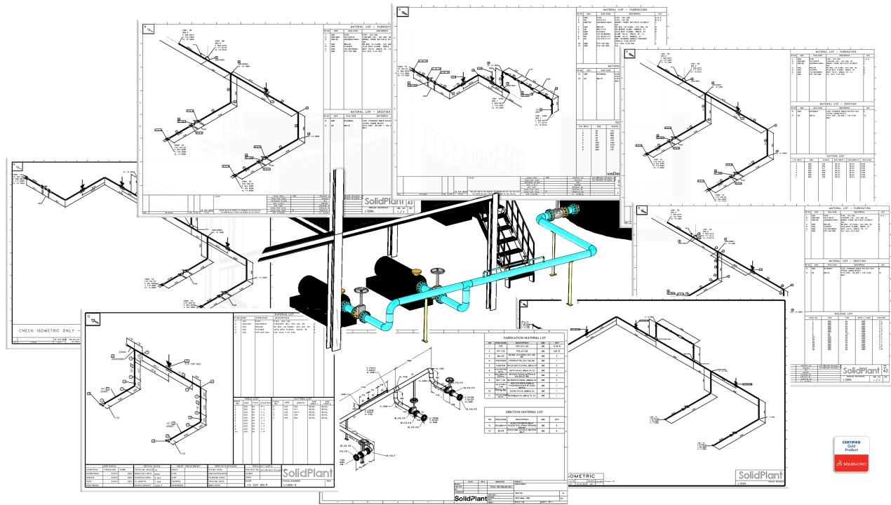
How to create piping isometric drawings with SOLIDWORKS

Piping Isometric Drawing at Explore collection of

Sample Iso Piping Drawing
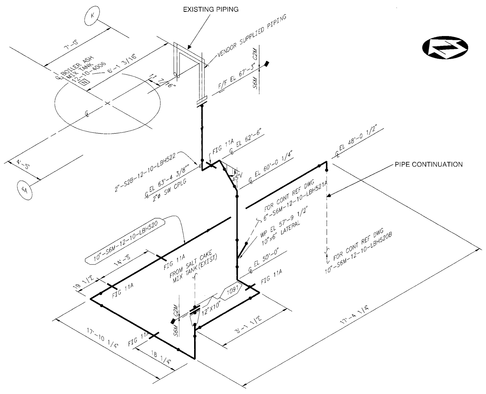
Reading isometric pipe drawings panrewa
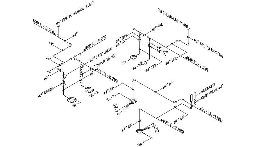
Isometric Pipe Line CAD Drawing Free Download DWG File Cadbull
Automatic Piping Isometrics from 3D Piping Designs M4 ISO
Piping Isometric Drawing at Explore collection of
Web Pipeline Isometric Drawings Are Crucial Visual Representations In The Fields Of Engineering And Construction.
Web A Piping Isometric Drawing Is A Technical Illustration That Presents A 3D Representation Of A Piping System.
Check The Annotation's Block Name.
Work From Hand Sketches Or Just Draw Them Directly.
Related Post:
