Pid Drawing Symbols
Pid Drawing Symbols - They are typically created by engineers who are designing a manufacturing process for a physical plant. Web p&id and pfd symbols. With download pdf for free. Process flow diagram (pfd) or process flow scheme (pfs) piping & instrument diagram (p&id) or process flow engineering scheme (pefs) process & instrument diagram. Solid lines for process pipes, dashed lines for instrument signals, etc. Pumps and tanks come in a variety of designs and shapes. Web some commonly used symbols in p&id diagrams include: Insertion point set to zero 0 of the flange and. Web piping and instrument diagram standard symbols detailed documentation provides a standard set of shapes & symbols for documenting p&id and pfd, including standard shapes of instrument, valves, pump, heating exchanges, mixers, crushers, vessels, compressors, filters, motors and connecting shapes. Remember that p&ids represent the hardware and software necessary to design, build, and run a process industry facility. Web what are p&id symbols. Web piping and instrumentation diagrams (p&ids) use specific instrumentation symbols to show the connectivity of equipment, piping, sensors, and valves within a control system, and they are most commonly used in engineering. Remember that p&ids represent the hardware and software necessary to design, build, and run a process industry facility. Your list should include all. All components are represented using various p&id symbols. Web a piping and instrumentation diagram (p&id) is a graphic representation of a process system that includes the piping, vessels, control valves, instrumentation, and other process components and equipment in the system. Your list should include all piping elements, including the order and placement of: These instrumentation symbols can represent actuators, sensors,. Process flow diagram (pfd) or process flow scheme (pfs) piping & instrument diagram (p&id) or process flow engineering scheme (pefs) process & instrument diagram. Web piping and instrument diagram standard symbols detailed documentation provides a standard set of shapes & symbols for documenting p&id and pfd, including standard shapes of instrument, valves, pump, heating exchanges, mixers, crushers, vessels, compressors, filters,. Web p&id and pfd drawing symbols and legend list. They are typically created by engineers who are designing a manufacturing process for a physical plant. P&id is an abbreviation meaning ‘ piping and instrumentation diagram ‘. Web a piping and instrumentation diagram (p&id) is defined as follows: Web piping and instrumentation diagrams (p&ids) use specific instrumentation symbols to show the. Solid lines for process pipes, dashed lines for instrument signals, etc. Additionally, at the article’s conclusion, there’s a pdf file containing the most critical p&id symbols employed in process and plant engineering available for your use. Web piping and instrumentation diagrams (p&ids) use specific symbols to show the connectivity of equipment, sensors, and valves in a control system. Pumps and. Web the common p&id symbols are listed here: Web the instrument p&id symbols can be: In this video, you will learn. A diagram which shows the interconnection of process equipment and the instrumentation used to control the process. Here you can find what information is contained on a p&id. P&id is an abbreviation meaning ‘ piping and instrumentation diagram ‘. To create such a comprehensive design, start by listing the elements in a standard p&id. Your list should include all piping elements, including the order and placement of: Web a piping and instrumentation diagram (p&id) is a graphic representation of a process system that includes the piping, vessels, control. There is an article to introduce p&id symbols. Web p&id symbols can be broadly classified into 7 categories: Gate valve, globe valve, check valve, ball valve, butterfly valve, etc. These diagrams provide a map for the engineering system's design which is helpful to problem identification and solving. There are few iso and british standards available that provide symbols and best. Web like all other professional diagrams, p&ids has standard shapes and symbols. Pumps and tanks come in a variety of designs and shapes. They are typically created by engineers who are designing a manufacturing process for a physical plant. Represented as a square containing an arrow or line, signifying control of flow or pressure. As this diagram covers many types. In this video, you will learn. These instrumentation symbols can represent actuators, sensors, and controllers. Here you can find what information is contained on a p&id. Web the instrument p&id symbols can be: Let us look at some of the most famous symbols suitable for smooth functioning across the industry. Web p&ids are a schematic illustration of the functional relationship of piping, instrumentation and system equipment components used in the field of instrumentation and control or automation. Additionally, at the article’s conclusion, there’s a pdf file containing the most critical p&id symbols employed in process and plant engineering available for your use. Web some commonly used symbols in p&id diagrams include: All components are represented using various p&id symbols. Web how to draw a piping & instrumentation diagram? So that blind flange will be connected to pipeline segments and get properties of it in the data manager. Gate valve, globe valve, check valve, ball valve, butterfly valve, etc. A single pfd can have multiple p&ids. Web how to connect flange and blind flange symbols on pid pipeline segments in autocad plant 3d. Data manager view of pipeline connected with flange and blind flange. Storage tanks, reactors, columns, drums, etc. P&id diagrams are made with specific and standard shapes and symbols. Web a p&id or process and instrumentation diagram provides a detailed graphical representation of the actual process system that includes the piping, equipment, valves, instrumentation, and other process components in the system. Web like all other professional diagrams, p&ids has standard shapes and symbols. These symbols can represent actuators, sensors, and controllers and may be. Web looking for a library of common p&id symbols?
P&ID Symbols & Abbreviations Piping Analysis YouTube
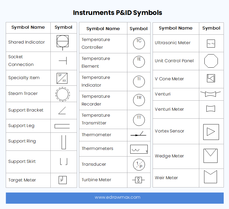
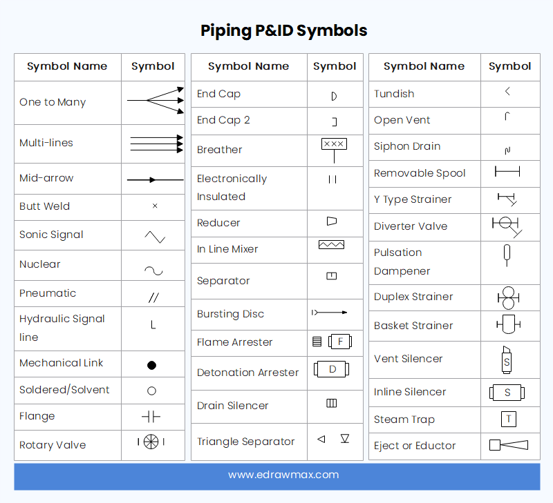
P&ID Symbols and Meanings EdrawMax Online

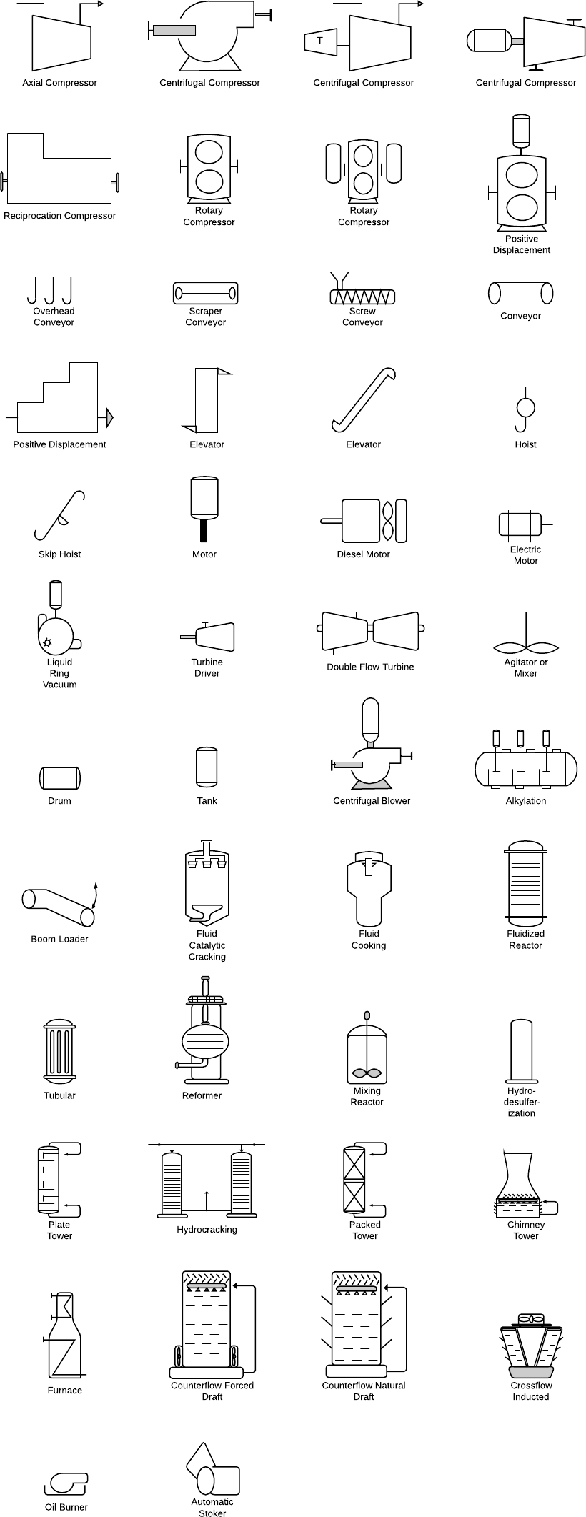
P&ID and PFD Drawing Symbols and Legend list (PFS & PEFS)
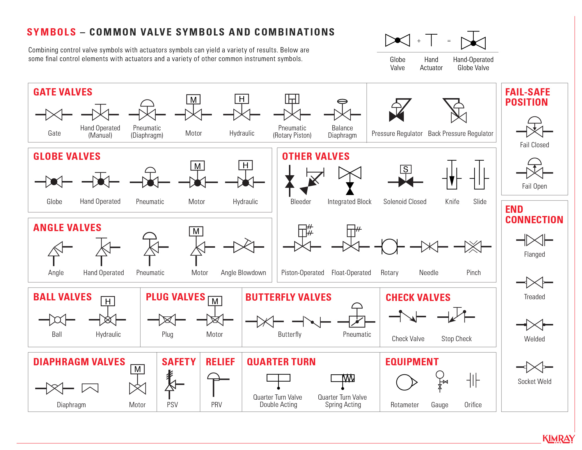
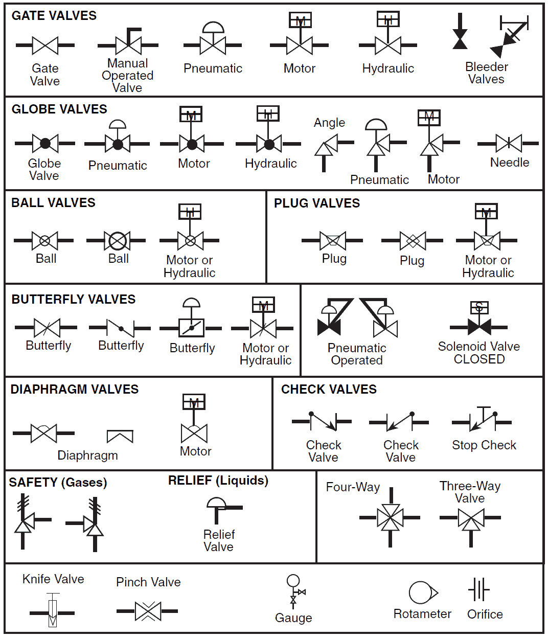
How to Read Oil and Gas P&ID Symbols Kimray
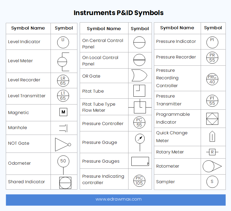
P&ID Symbols and Meanings EdrawMax Online
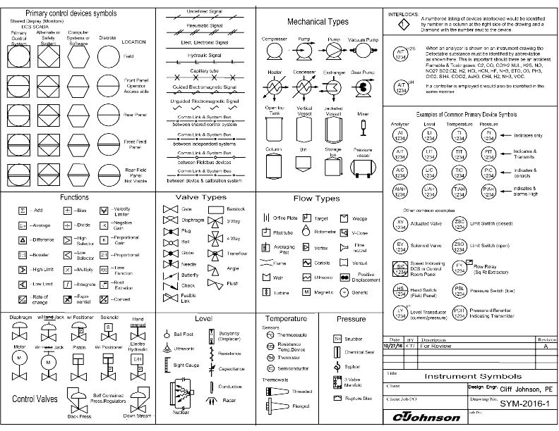
P&ID Symbols and Notation By
What is a P&ID Beginner’s Guide EdrawMax Online
P&ID and PFD Drawing Symbols and Legend list (PFS & PEFS)
P&ID Symbols and Control Links

P&ID Symbols and Notation Lucidchart
With Download Pdf For Free.
Let Us Look At Some Of The Most Famous Symbols Suitable For Smooth Functioning Across The Industry.
Depicted As A Circle With A Dot Inside, Indicating Temperature Measurement At A Specific Point In The System.
Web Piping And Instrumentation Diagrams (P&Ids) Use Specific Symbols To Show The Connectivity Of Equipment, Sensors, And Valves In A Control System.
Related Post: