Manufacturing Process Drawing
Manufacturing Process Drawing - 4 why you need accuracy and precision in technical drawing. Web a process flow diagram (pfd) is a type of flowchart that illustrates the relationships between major components at an industrial plant. Web these drawings provide a detailed representation of how various components come together to form a complete assembly, guiding manufacturers, engineers, and stakeholders through the production process. Drawing is classified into two types: These best practices apply to 2d drafting and creating technical drawings from a 3d model. Drawing is a metal forming process used to reduce cross section and increase length of work piece. Machine operators, production line workers and supervisors all use production. Web metal drawing is a manufacturing process that forms metal work stock by reducing its cross section. These drawings are essentially the blueprints or plans for manufacturing a wide array of products and structures. Web sheet metal drawing, a crucial manufacturing process, stands as a cornerstone in the creation of hollow, multifaceted components with a sharp focus on precision. The “routing” is a combination of the bill of material and the process flow. 5 the future of 2d and 3d drawings in manufacturing. 5 applications of technical drawing in machining processes. Before 3d cad software became commonplace, 2d drawings were the norm in the manufacturing industry. It’s not an easy trip, but these eight steps help make it possible: • green design, sustainable manufacturing, product life cycle. Before 3d cad software became commonplace, 2d drawings were the norm in the manufacturing industry. Web 4.1 key factors to consider while choosing between 2d and 3d. It clearly defines the part’s design, final quality, manufacturing processes, component materials, ease of distribution, etc. Web sheet metal drawing, a crucial manufacturing process, stands. Consult the manufacturer before producing detailed drawings. • design for manufacturing, assembly, disassembly, service. Web this chapter is divided into sections on: In this comprehensive guide, we will explore the key steps and best practices involved in creating effective assembly drawings in. Before 3d cad software became commonplace, 2d drawings were the norm in the manufacturing industry. These best practices apply to 2d drafting and creating technical drawings from a 3d model. Machine operators, production line workers and supervisors all use production. When possible draw parts to a 1:1 scale and print to get a real sense of size. Web metal drawing is a manufacturing process that forms metal work stock by reducing its cross section. The. This is accomplished by forcing the work through a mold, (die), of smaller cross sectional area than the work. It’s not an easy trip, but these eight steps help make it possible: Web today we will learn about drawing process working and its types like wire drawing, rod drawing and tube drawing. Beverage cans, automotive panels, bathtubs, pots, pans, and. A variety of different types of engineering drawings exist: Web streamlined product development process. Web the main purpose of production drawings is to define the size, shape, location and production of the component. Web in this article we will cover the basics of creating high quality engineering drawings for individual part designs so that you can communicate your design and. In this comprehensive guide, we will explore the key steps and best practices involved in creating effective assembly drawings in. Web 4.1 key factors to consider while choosing between 2d and 3d. Web sheet metal drawing, a crucial manufacturing process, stands as a cornerstone in the creation of hollow, multifaceted components with a sharp focus on precision. It clearly defines. Web the main purpose of production drawings is to define the size, shape, location and production of the component. Sheet metal drawing and wire, bar, and tube drawing. Steps of the manufacturing process. 5 applications of technical drawing in machining processes. These drawings are essentially the blueprints or plans for manufacturing a wide array of products and structures. What are the steps that take an idea and turn it into a reality? Web 18.06.2020 by andreas velling. Steps of the manufacturing process. 4 why you need accuracy and precision in technical drawing. Web drawing process is based on micropipette or glass rod application to obtain a desired structure. In this comprehensive guide, we will explore the key steps and best practices involved in creating effective assembly drawings in. It’s used to document a process, improve a process or model a new one. Beverage cans, automotive panels, bathtubs, pots, pans, and sinks. Engineering drawings use standardised language and symbols. Web today we will learn about drawing process working and. The sharp tip of a micropipette contacts with a polymer solution droplet and subsequent withdraw slowly which leads to producing nanofibers. Design for manufacturing starts with the big picture in mind. 4 why you need accuracy and precision in technical drawing. Web streamlined product development process. It’s used to document a process, improve a process or model a new one. This technique is instrumental in the production of a diverse range of items we frequently encounter, be it in household goods or specialized industrial equipment. • design for manufacturing, assembly, disassembly, service. Web 4.1 key factors to consider while choosing between 2d and 3d. When possible draw parts to a 1:1 scale and print to get a real sense of size. 9/16/2022 | 5 min read. Web this chapter is divided into sections on: The purpose is to convey all the information necessary for manufacturing a product or a part. This is accomplished by forcing the work through a mold, (die), of smaller cross sectional area than the work. Sheet metal drawing and wire, bar, and tube drawing. Web the main purpose of production drawings is to define the size, shape, location and production of the component. Drawing is a metal forming process used to reduce cross section and increase length of work piece.![[DIAGRAM] Process Flow Diagram Manufacturing](http://image.slideserve.com/218052/production-process-flow-diagram-l.jpg)
[DIAGRAM] Process Flow Diagram Manufacturing
![[DIAGRAM] Process Flow Diagram Manufacturing](http://www.presentationeze.com/wp-content/uploads/2015/01/Manufacturing-Process-Flow-Chart.jpg)
[DIAGRAM] Process Flow Diagram Manufacturing
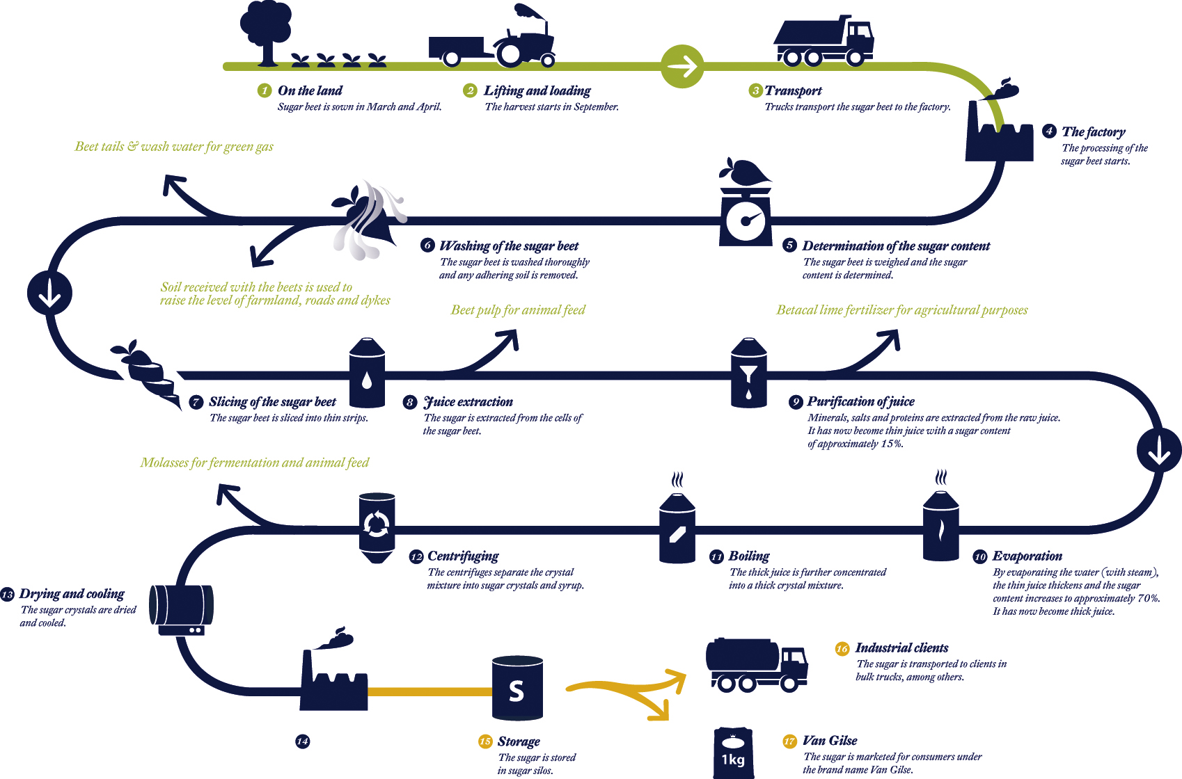
PRODUCTION PROCESS and PROCESS PLANNING Engineers Gallery
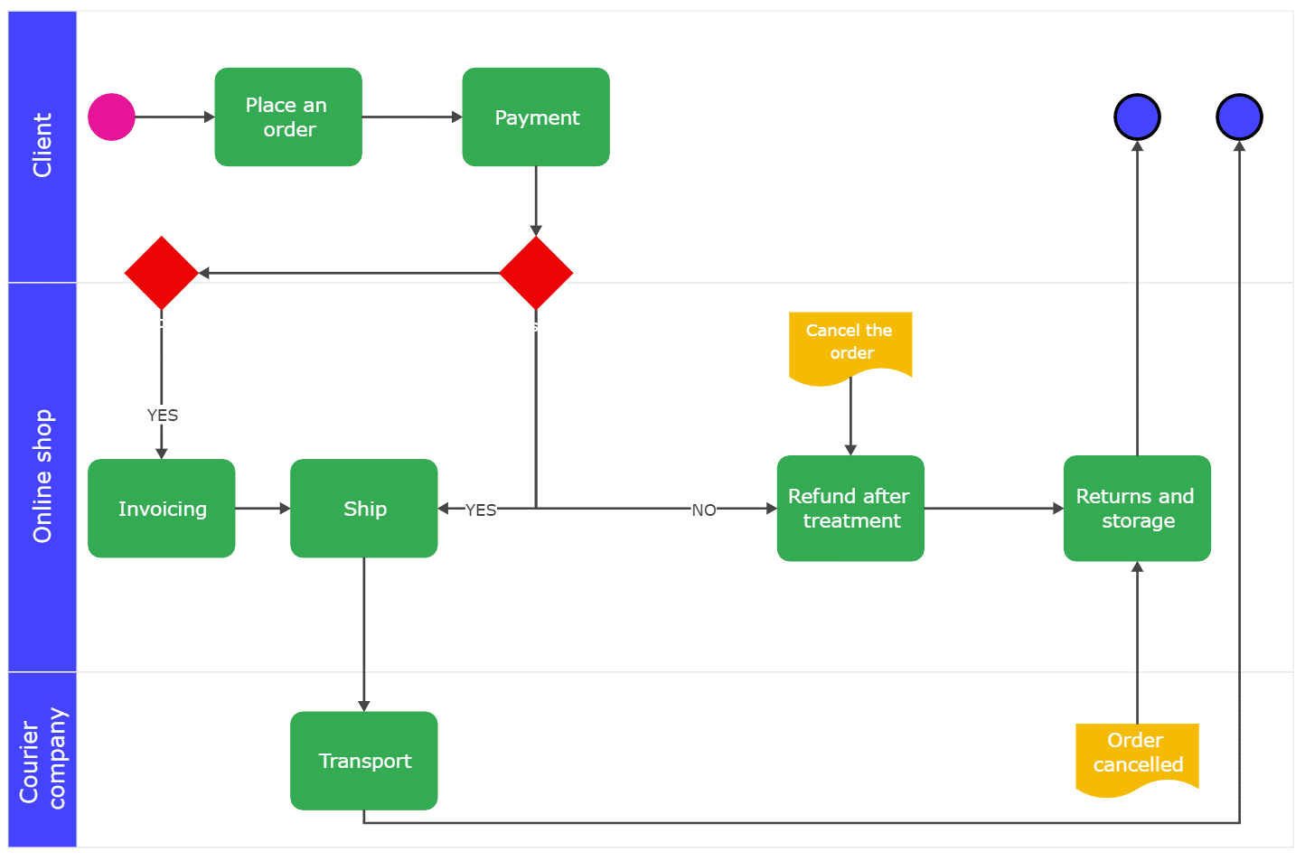
Understanding Manufacturing Process Flowcharts (With Examples)
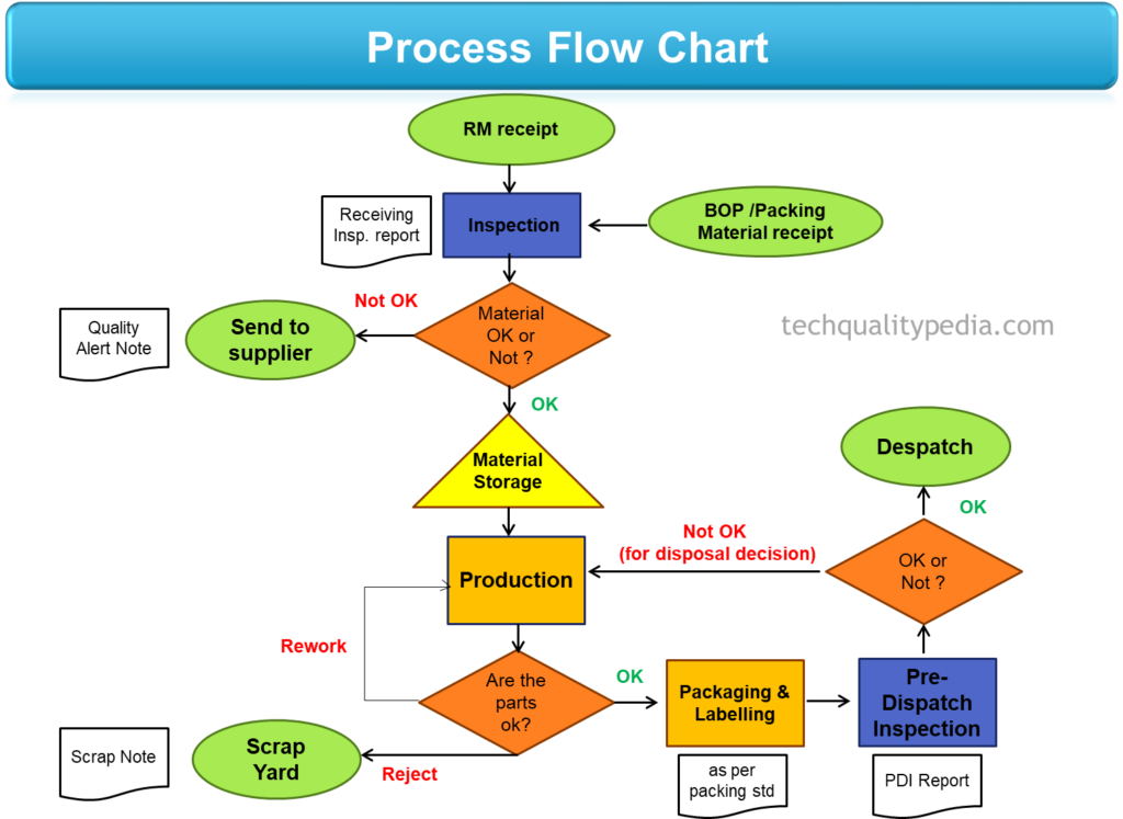
Process flow chart in manufacturing Symbols for process flow chart

Manufacturing Process Chart Stock Vector Image & Art Alamy

Understanding Manufacturing Process Flowcharts (With Examples)

Manufacturing Process Planning Flow Chart Examples
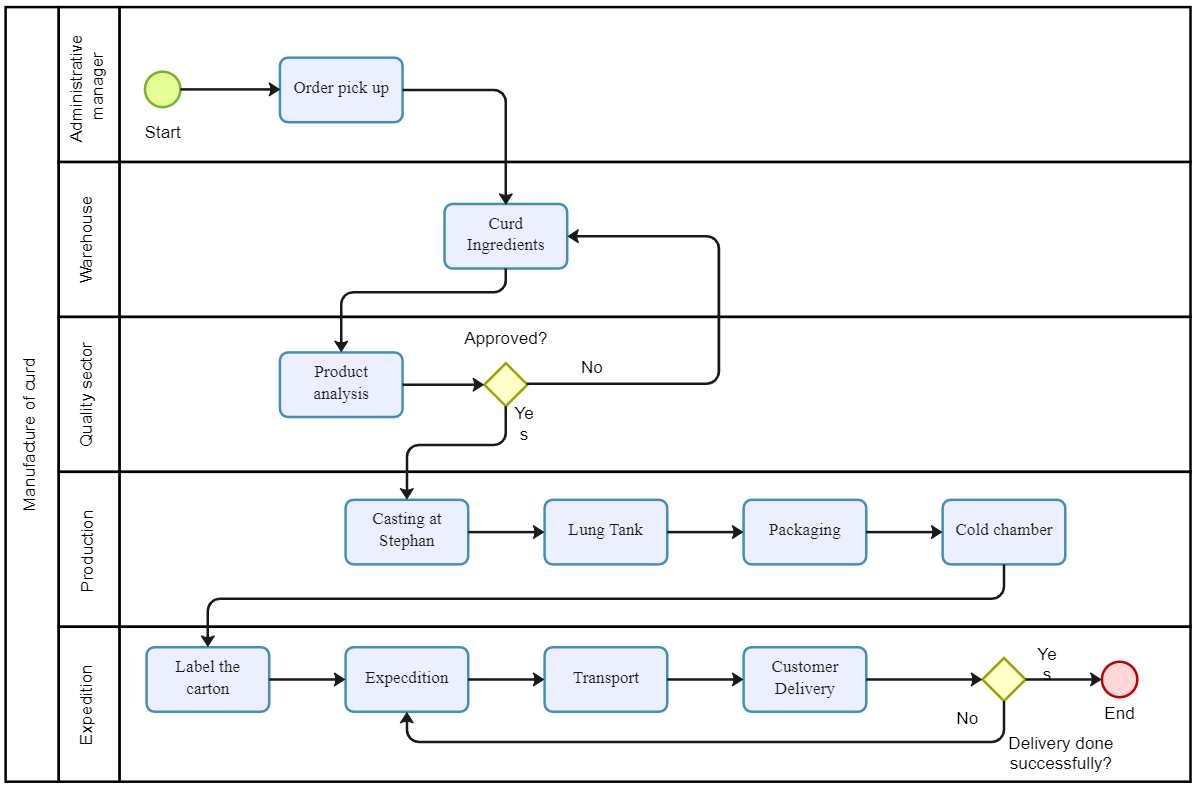
Understanding Manufacturing Process Flowcharts (With Examples)
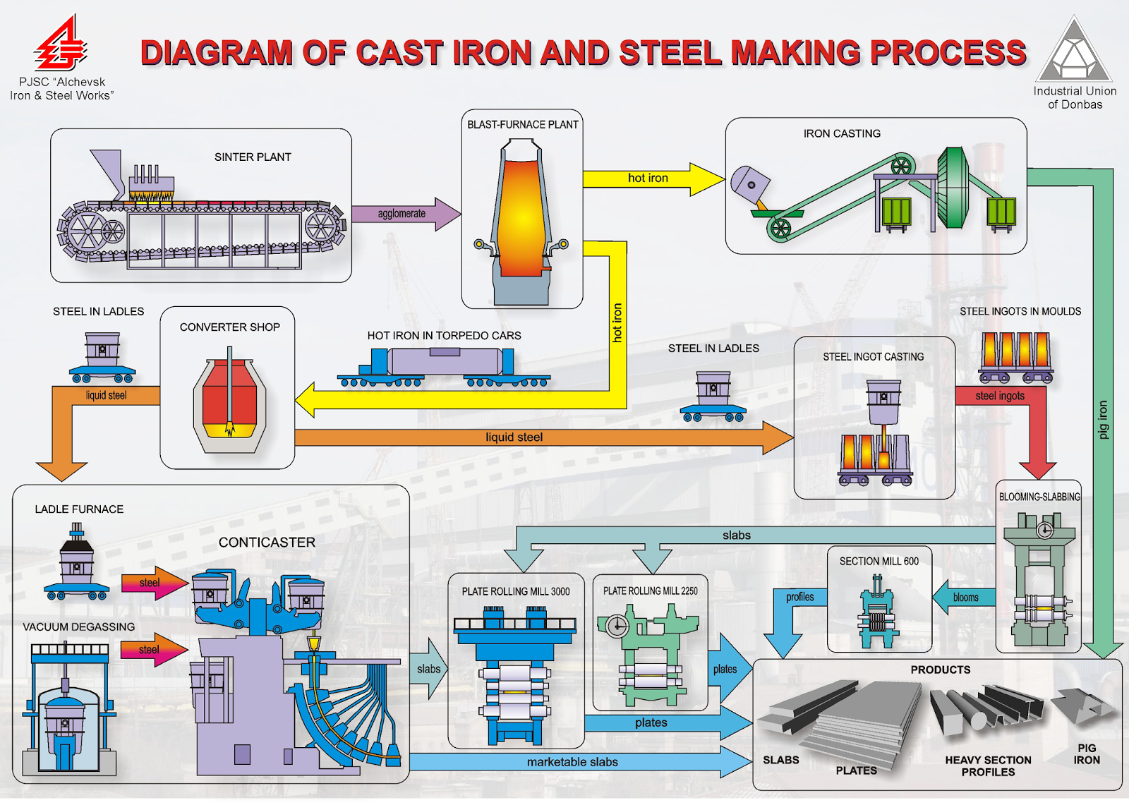
Current Steel Manufacturing Process Metallurgy Materials
An Engineering Drawing Is A Subcategory Of Technical Drawings.
• Green Design, Sustainable Manufacturing, Product Life Cycle.
This Process Is Very Similar To Metal Extrusion, The Difference Being In The Application Of Force.
As The Material Is Drawn (Pulled), It Stretches And Becomes Thinner, Achieving A Desired Shape And Thickness.
Related Post: