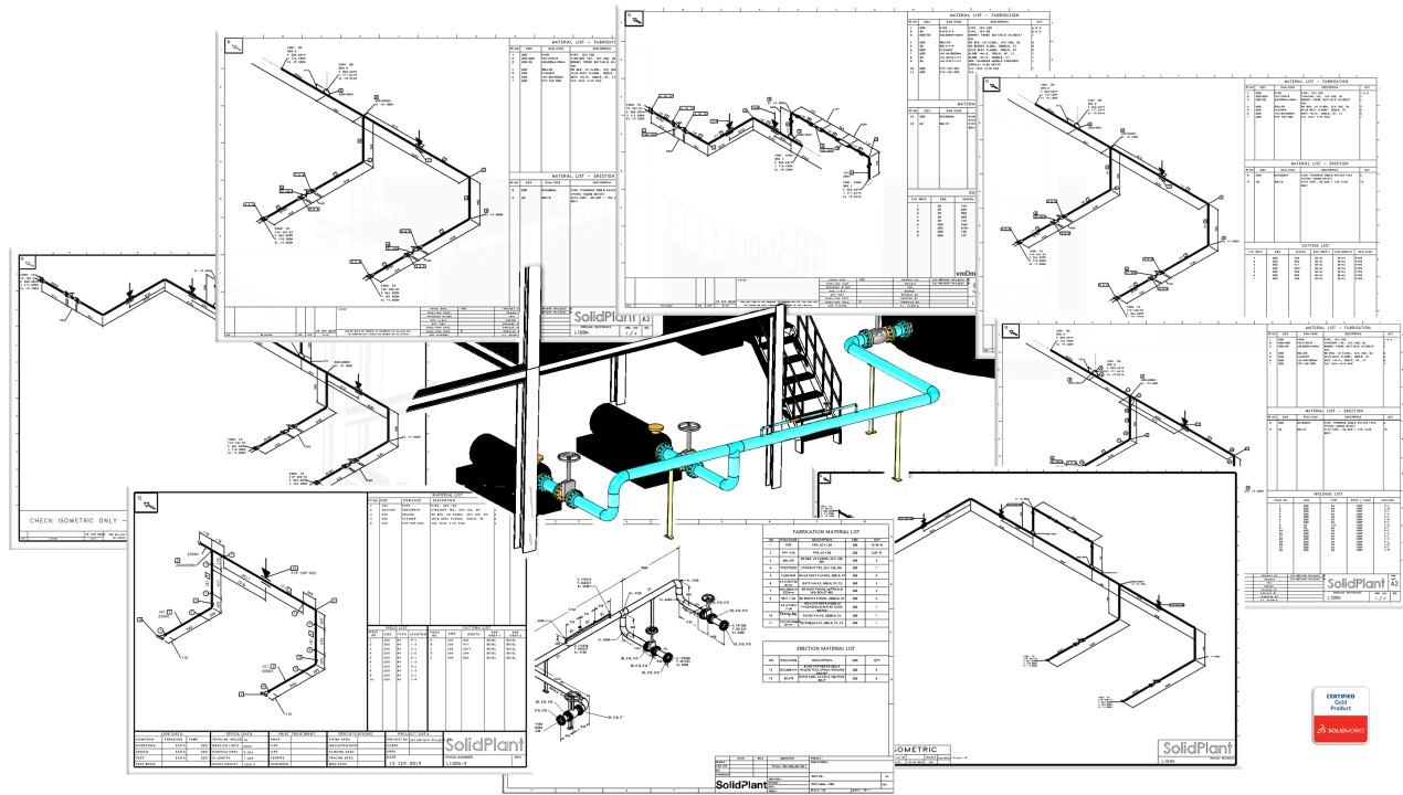
Isometric Pipeline Drawing
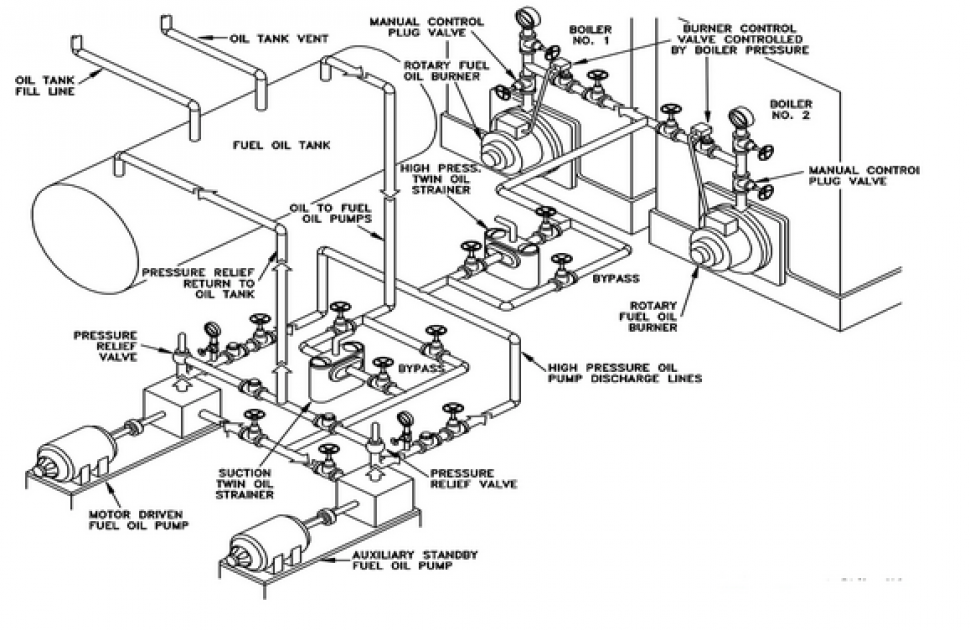
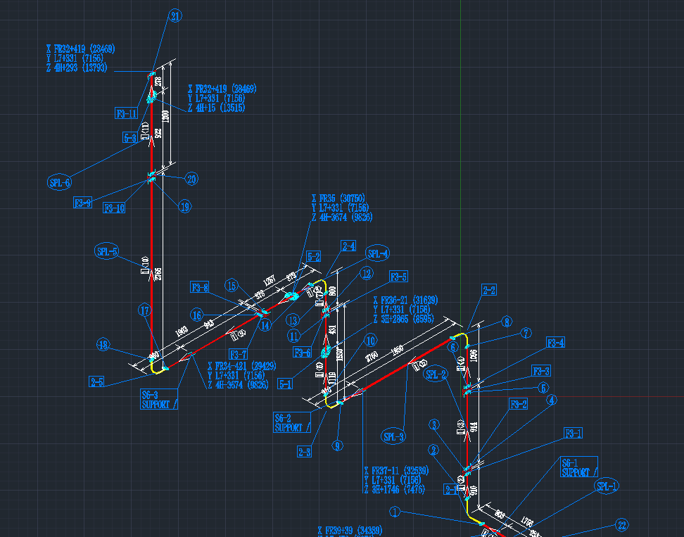
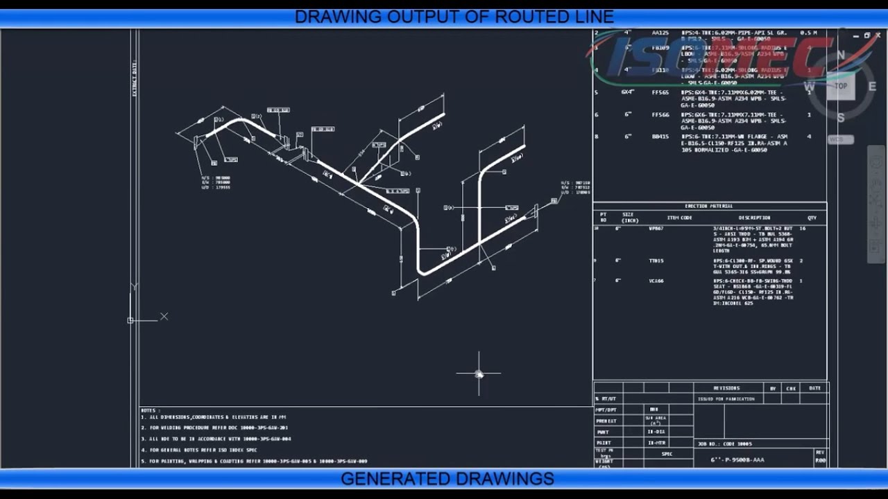
Isometric Pipeline Drawing - / mechanical termonology / by grow mechanical. Web for reading any piping isometric drawing you must have to familiar with these 04 important things: 1) show all major equipment, its north/south and east/west orientation, and all piping leading to and from equipment are developed by piping designers. Piping isometric drawing is a representation of 3d view of piping layout of the plant. Web creating a piping isometric drawing. No more tedious material tracking when creating a pipe isometric drawing. 3 clicks to draw a pipe, 3 clicks to add an elbow, 1 click to add a dimension and 3 clicks to print. Web guide to piping design and isometric drawings pdf. The command scale can be used to. The main body of an isometric piping drawing consists of the following: Type the command bedit and change the block identified in step 7. 1) show all major equipment, its north/south and east/west orientation, and all piping leading to and from equipment are developed by piping designers. Create isometric drawings in minutes: Web a piping isometric drawing is a technical drawing that depicts a pipe spool or a complete pipeline using an. The main body of an isometric piping drawing consists of the following: Each serves a unique purpose and offers different perspectives to engineers, designers, and builders, ensuring a comprehensive understanding of the piping system’s layout, design, and functionality. 1) show all major equipment, its north/south and east/west orientation, and all piping leading to and from equipment are developed by piping. Open windows explorer and go to the isometric folder in your project. Piping isometric drawings are detailed technical illustrations that show a 3d view of piping systems. Web easy isometric is the first pipe isometric drawing app that helps users make detailed isometric drawings in the field and without the need for tedious reference materials. Web isometric drawings are, by. Web guide to piping design and isometric drawings pdf. So, not from the outside of a pipe or fitting. Managing piping isometrics with the isometric tracker. Web isometric, plan, and elevation presentations are three distinct types of drawings used to depict piping systems in engineering and construction. Web pipeline isometric drawings are crucial visual representations in the fields of engineering. Piping isometric drawing is a representation of 3d view of piping layout of the plant. These drawings provide a detailed 3d illustration of a piping system, offering a comprehensive view of. The main body of an isometric piping drawing consists of the following: Piping isometric drawing consists of three sections. / mechanical termonology / by grow mechanical. These tools generate the 3d representation of the piping layout, including pipe dimensions, fittings,. Import idf or pcf files. 3 clicks to draw a pipe, 3 clicks to add an elbow, 1 click to add a dimension and 3 clicks to print. Web easy isometric is the first pipe isometric drawing app that helps users make detailed isometric drawings in. The piping isometrics life cycle. Web go to skew > slopesymbols > ratio. Open windows explorer and go to the isometric folder in your project. 3 clicks to draw a pipe, 3 clicks to add an elbow, 1 click to add a dimension and 3 clicks to print. Piping plan drawings/general arrangement drawings (gad) the piping plan or general arrangement. Web how to read piping isometric drawing symbols. Each serves a unique purpose and offers different perspectives to engineers, designers, and builders, ensuring a comprehensive understanding of the piping system’s layout, design, and functionality. Web isometric drawings are typically used to show the details of a piping system, such as the size and type of piping, the direction of flow. Enhancing data analysis for piping isometrics. Web piping isometric drawing software is an essential tool for piping engineers and designers to create detailed isometric drawings of piping systems. Open windows explorer and go to the isometric folder in your project. Web an isometric drawing is a type of pictorial drawing in which three sides of an object can be seen. Iso pipes are typically drawn using specialized software such as avicad which supports isometric drawings. The command scale can be used to. These drawings are particularly useful for understanding how the pipeline moves through space, which helps in planning inspections in complex or tight areas. Web how to read piping isometric drawing symbols. Web an isometric drawing is a type. Each serves a unique purpose and offers different perspectives to engineers, designers, and builders, ensuring a comprehensive understanding of the piping system’s layout, design, and functionality. Web a pipe into a isometric view, is always drawn by a single line. Web drawing piping isometrics : Web go to skew > slopesymbols > ratio. Data extraction and analysis for piping isometrics. Iso pipes are typically drawn using specialized software such as avicad which supports isometric drawings. Piping isometric drawing consists of three sections. Web isometric drawings are typically used to show the details of a piping system, such as the size and type of piping, the direction of flow of the fluids, and the location of valves, pumps, and other equipment nozzles. Web what are pipeline isometric drawings? This single line is the centerline of the pipe, and from that line, the dimensions measured. The command scale can be used to. Type the command bedit and change the block identified in step 7. Web piping isometric drawing software is an essential tool for piping engineers and designers to create detailed isometric drawings of piping systems. Managing piping isometrics with the isometric tracker. 1) show all major equipment, its north/south and east/west orientation, and all piping leading to and from equipment are developed by piping designers. Piping fabrication work is based on isometric drawings.How to create piping isometric drawings with SOLIDWORKS

How to read isometric drawing piping dadver

Isometric Piping Drawings Advenser
Pipeline Isometric Drawings Explained NDT Techniques & Interpretation

How to read piping Isometric drawing YouTube
Piping isometric drawing examples mazorama
Piping Isometric Drawing at Explore collection of

How to read piping isometric drawing, Pipe fitter training, Watch the

How to Draw Isometric Pipe Drawings in Autocad Gautier Camonect

How to read isometric drawing piping dadver
Web Pipeline Isometrics Are Detailed Drawings Used In Engineering And Design To Represent The 3D Layout Of A Pipeline System On A 2D Surface.
In The Context Of Piping Symbols, Isometrics Allow Engineers, Designers, And Technicians To Convey The Intricate Details Of A System Effectively.
These Highly Structured Drawings Provide A Comprehensive 3D Representation Of The Arrangement, Dimensions, And Connections Of Pipes Within A System.
/ Mechanical Termonology / By Grow Mechanical.
Related Post: