Iso Drawings
Iso Drawings - Basic convention for lines part 21: Microfilming of technical drawings and other drawing office documents — part 3: Microfilming of drawings of special and exceptional elongated sizes. Electrical and electronics engineering drawings. Web guidelines on the language, formatting and presentation of iso documents. Web iso 7518:1983 technical drawings — construction drawings — simplified representation of demolition and rebuilding iso 7519:1991 technical drawings — construction drawings — general principles of presentation for general arrangement and assembly drawings Web chapter 1 drawing notation and default tolerances. Technical drawings for telecommunications and information technology fields. Preparation of lines by cad systems 1.5 table and drawing field. Microfilming of technical drawings and other drawing office documents — part 3: Web guidelines on the language, formatting and presentation of iso documents. Microfilming of technical drawings and other drawing office documents — part 4: Preparation of lines by cad systems The indications included on an iso 10110 optical drawing are defined, and an example drawing is provided to illustrate. Including electrical tables, diagrams and charts. Web iso 7518:1983 technical drawings — construction drawings — simplified representation of demolition and rebuilding iso 7519:1991 technical drawings — construction drawings — general principles of presentation for general arrangement and assembly drawings Basic convention for lines part 21: Aperture card for 35 mm microfilm. Iso drafting made efficient [pdf] how to draft iso. Basic convention for lines part 21: Microfilming of technical drawings and other drawing office documents — part 3: Iso 128 consists of the following parts, under the general title technical drawings— general principles of presentation: Web chapter 1 drawing notation and default tolerances. Technical drawings for telecommunications and information technology fields. Web guidelines on the language, formatting and presentation of iso documents. 1.5 table and drawing field. Iso drafting made efficient [pdf] how to draft iso documents efficiently, making them easier to read and implement. Electrical and electronics engineering drawings. Preparation of lines by cad systems Iso drafting made efficient [pdf] how to draft iso documents efficiently, making them easier to read and implement. 1.2 differences between iso and us standards. The indications included on an iso 10110 optical drawing are defined, and an example drawing is provided to illustrate how the information is commonly presented. Technical drawings for telecommunications and information technology fields. Electrical and. Basic convention for lines part 21: Technical drawings for telecommunications and information technology fields. Electrical and electronics engineering drawings. 1.3 overview of coded notation. Web chapter 1 drawing notation and default tolerances. Microfilming of technical drawings and other drawing office documents — part 3: 1.2 differences between iso and us standards. Including electrical tables, diagrams and charts. Microfilming of drawings of special and exceptional elongated sizes. Web guidelines on the language, formatting and presentation of iso documents. Electrical and electronics engineering drawings. 1.5 table and drawing field. Microfilming of technical drawings and other drawing office documents — part 3: Features of piping isometric drawing. Web chapter 1 drawing notation and default tolerances. Web chapter 1 drawing notation and default tolerances. Iso drafting made efficient [pdf] how to draft iso documents efficiently, making them easier to read and implement. Web iso 7518:1983 technical drawings — construction drawings — simplified representation of demolition and rebuilding iso 7519:1991 technical drawings — construction drawings — general principles of presentation for general arrangement and assembly drawings Electrical. Microfilming of technical drawings and other drawing office documents — part 3: Web guidelines on the language, formatting and presentation of iso documents. Basic convention for lines part 21: Preparation of lines by cad systems Aperture card for 35 mm microfilm. Iso drafting made efficient [pdf] how to draft iso documents efficiently, making them easier to read and implement. Web guidelines on the language, formatting and presentation of iso documents. 1.3 overview of coded notation. Microfilming of technical drawings and other drawing office documents — part 3: 1.5 table and drawing field. Web iso 7518:1983 technical drawings — construction drawings — simplified representation of demolition and rebuilding iso 7519:1991 technical drawings — construction drawings — general principles of presentation for general arrangement and assembly drawings Microfilming of technical drawings and other drawing office documents — part 4: The indications included on an iso 10110 optical drawing are defined, and an example drawing is provided to illustrate how the information is commonly presented. 1.2 differences between iso and us standards. Aperture card for 35 mm microfilm. Including electrical tables, diagrams and charts. Web this tutorial provides a brief introduction to the iso 10110 optical drawing standard. Web chapter 1 drawing notation and default tolerances. Technical drawings for telecommunications and information technology fields. Electrical and electronics engineering drawings. Features of piping isometric drawing.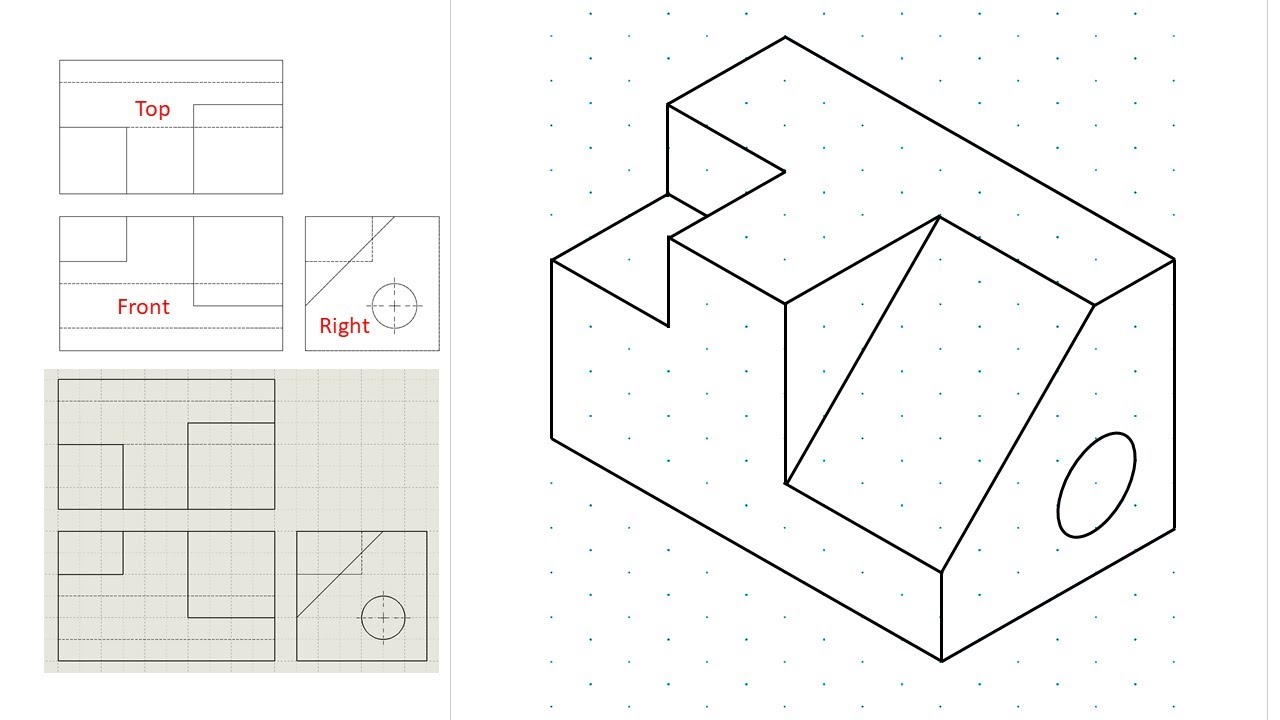
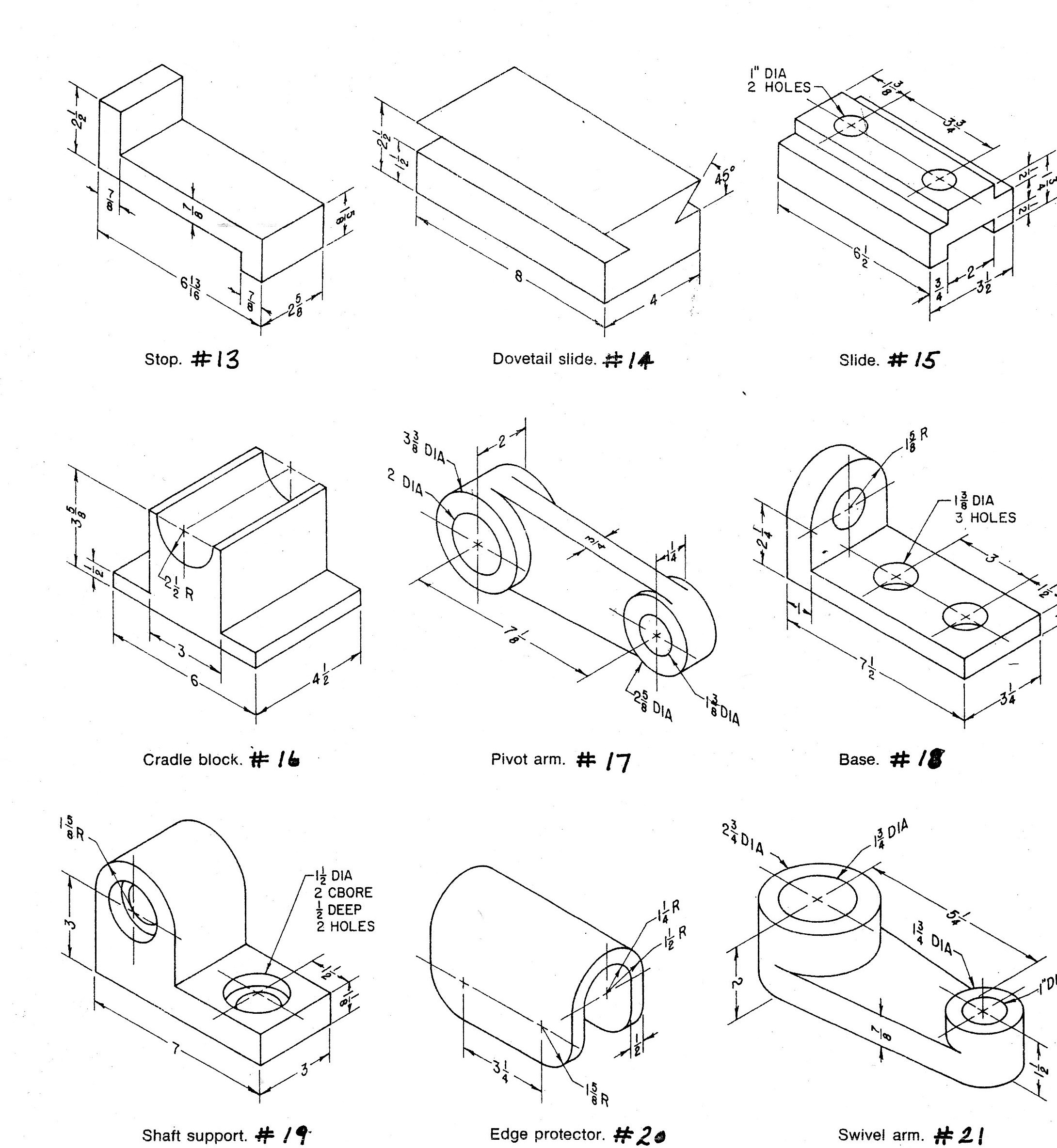
Isometric view drawing example 1 (easy). Links to practice files in
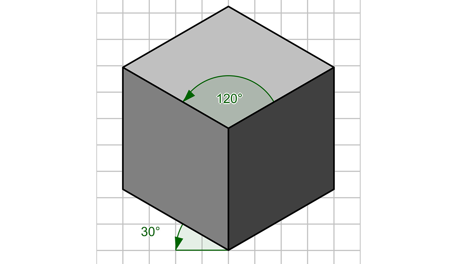
How To Construct An Isometric Drawing Joseph Ouldives

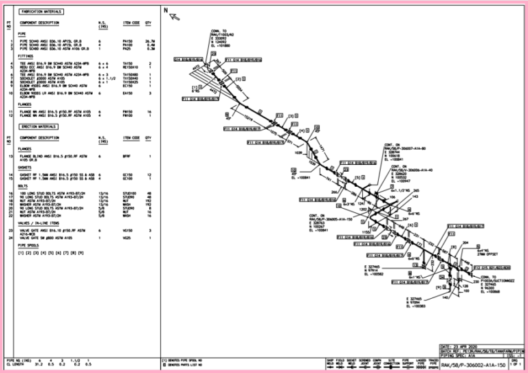
How to read iso drawings plmci
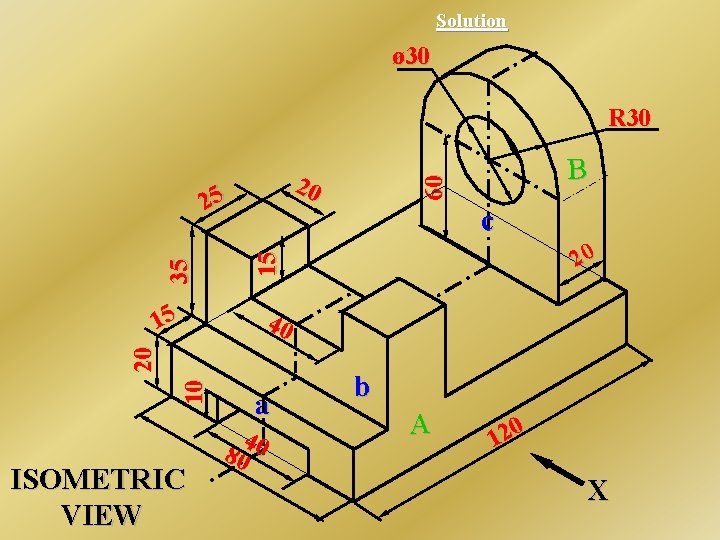
What is an Isometric Drawing? Types And Step To Draw
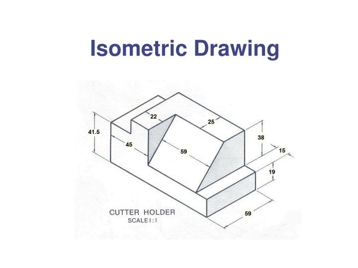
ISOMETRIC DRAWING Steps Involved in Isometric Drawing
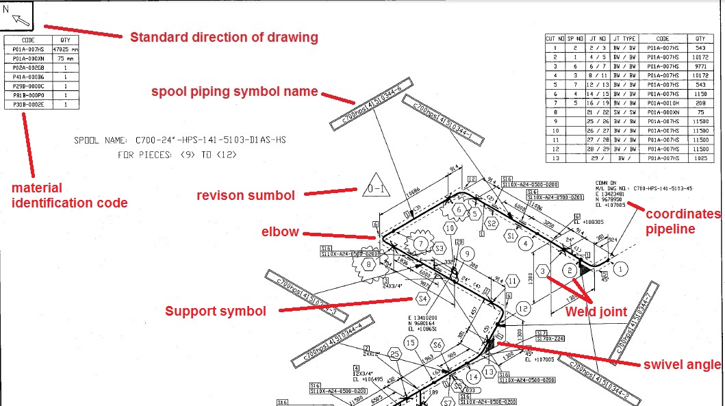
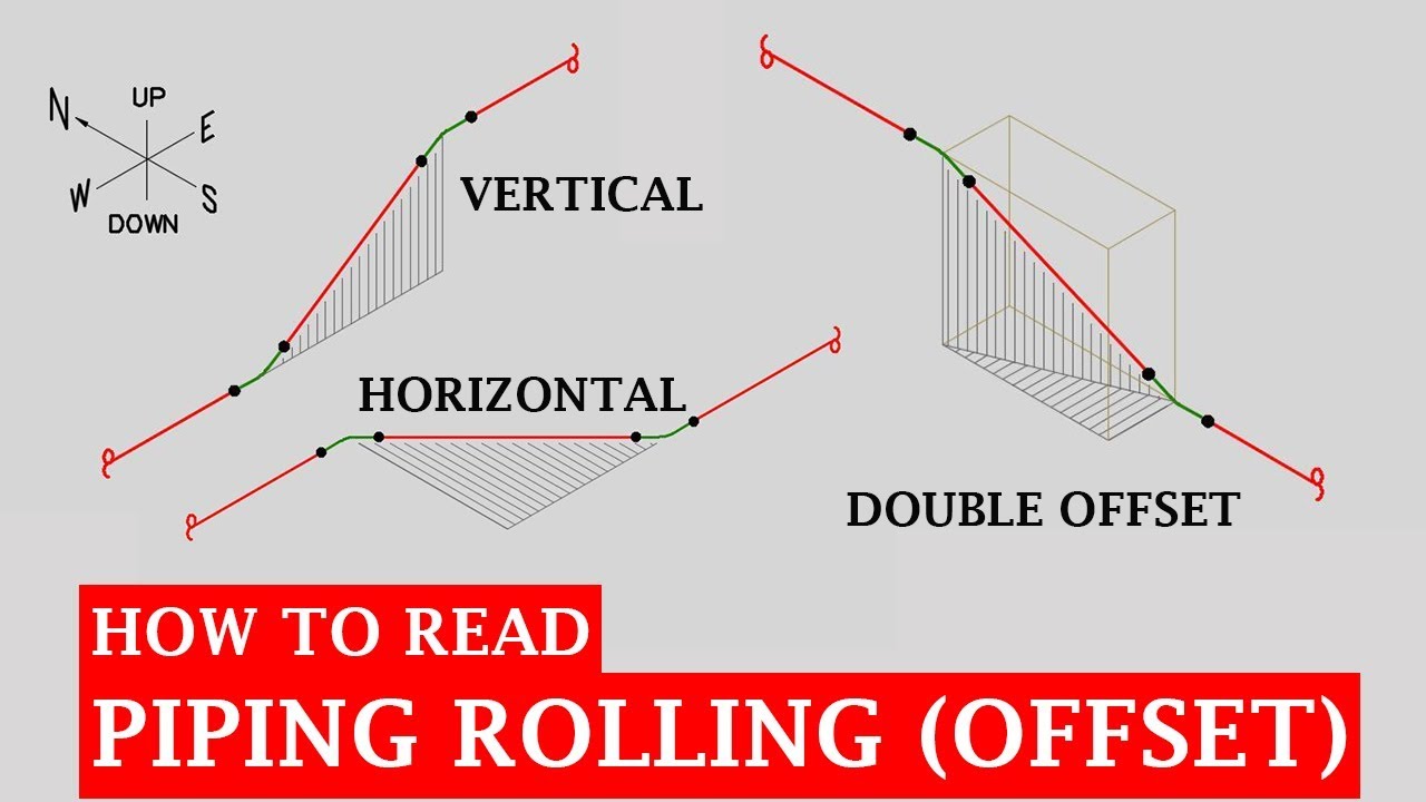
Learn isometric drawings (piping isometric)

How to read iso drawings plmci
Isometric Drawing at Explore collection of
How to read iso drawings daxarabia
How to read iso pipe drawings talentbda
Iso 128 Consists Of The Following Parts, Under The General Title Technical Drawings— General Principles Of Presentation:
Basic Convention For Lines Part 21:
Preparation Of Lines By Cad Systems
Microfilming Of Drawings Of Special And Exceptional Elongated Sizes.
Related Post: