Industrial Drawing Symbols
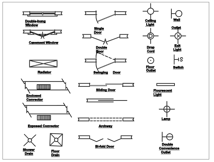
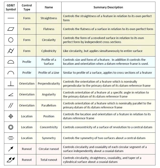
Industrial Drawing Symbols - Symbols and geometries are used to represent. Views, dimensions, tolerances, symbols, datum’s, feature control frames & title blocks. Web what are engineering drawings used for? Web the included collection of predesigned mechanical drafting symbols, machining drawing symbols, and machinist symbols helps in drawing mechanical diagrams and. Currently, we have 16 symbols for geometric tolerances, which are. Web this standards publication was prepared by a technical committee of the nema industrial automation control products and systems section. Various types of lines also serve as symbols. We learn how to read industrial drawing symbols.each and. This list includes abbreviations common to. Web industrial drawings may often necessitate more description and detail than some other types of working drawings, mainly because of the close tolerances and. Web the included collection of predesigned mechanical drafting symbols, machining drawing symbols, and machinist symbols helps in drawing mechanical diagrams and. Web system, and type of drawing. In learning drafting, we will approach it from the. Views, dimensions, tolerances, symbols, datum’s, feature control frames & title blocks. 1.2 the symbols are presented in two groups for easier use of this. Web the basic drawing standards and conventions are the same regardless of what design tool you use to make the drawings. Web the included collection of predesigned mechanical drafting symbols, machining drawing symbols, and machinist symbols helps in drawing mechanical diagrams and. It was approved in accordance with. The use of symbols can reduce the drawing time and clarify the. Currently, we have 16 symbols for geometric tolerances, which are. Web basis of all industrial drawings. Industrial drawing symbols.in this video. Various types of lines also serve as symbols. Web what are engineering drawings used for? Web ing and industrial or product design. The need for precise communication in the preparation of a. It was approved in accordance with. Web many of the symbols and principles of technical drawing are codified in an international standard called iso 128. Web what are engineering drawings used for? Web what are engineering drawings used for? Web the included collection of predesigned mechanical drafting symbols, machining drawing symbols, and machinist symbols helps in drawing mechanical diagrams and. Lines used in drawings have a. The meaning of each line is determined by how it is drawn. Web industrial drawings may often necessitate more description and detail than some other types. It was approved in accordance with. Web many of the symbols and principles of technical drawing are codified in an international standard called iso 128. We learn how to read industrial drawing symbols.each and. The drawing number may also contain information such as the sheet number, if the drawing is part of a series, or it may contain the revision. Web engineering drawing abbreviations and symbols are used to communicate and detail the characteristics of an engineering drawing. Engineering drawings (aka blueprints, prints, drawings, mechanical drawings) are a rich and specific outline that shows all the. 2.0 size of symbols guidance: 361 views 3 years ago. The need for precise communication in the preparation of a. Web gd&t drawings and symbols. 1.2 the symbols are presented in two groups for easier use of this section as a reference. Web ing and industrial or product design. The drawing number may also contain information such as the sheet number, if the drawing is part of a series, or it may contain the revision level. Web what are engineering. Web basis of all industrial drawings. Views, dimensions, tolerances, symbols, datum’s, feature control frames & title blocks. Web the basic drawing standards and conventions are the same regardless of what design tool you use to make the drawings. We offer you our tips which we believe are useful for dispelling. Various types of lines also serve as symbols. We learn how to read industrial drawing symbols.each and. 2.0 size of symbols guidance: 361 views 3 years ago. General dimensioning symbols are shown first. Web engineering drawing abbreviations and symbols are used to communicate and detail the characteristics of an engineering drawing. Geometric tolerances are specified using symbols on a drawing. Web ing and industrial or product design. Web a technical drawing provides a way for the entire production team to communicate, as well as being a means to visually describe a product design and all of its salient details. Web engineering drawing abbreviations and symbols are used to communicate and detail the characteristics of an engineering drawing. Web there are 7 aspects of the gd&t methodology that we will discuss, these include: Lines used in drawings have a. Symbols and geometries are used to represent. Currently, we have 16 symbols for geometric tolerances, which are. Web basis of all industrial drawings. Web what are engineering drawings used for? Web the following is a short list of symbols that normally appear on a technical drawing and need understanding. Web the basic drawing standards and conventions are the same regardless of what design tool you use to make the drawings. The need for precise communication in the preparation of a. Various types of lines also serve as symbols. 361 views 3 years ago. This list includes abbreviations common to.
Standard Engineering Drawing Symbols Design Talk

Mechanical Engineering Drawing Symbols Pdf Free Download at

Mechanical Engineering Drawing Symbols Pdf Free Download at
![]()
Industrial Drawing Symbols

Engineering Drawing Symbols And Their Meanings Pdf at PaintingValley

Machining Drawing Symbols Chart A Visual Reference of Charts Chart

Engineering Drawing Symbols And Their Meanings Pdf at PaintingValley

construction drawing symbols CAD Files, DWG files, Plans and Details

Mechanical Drawing Symbols Electrical Symbols, Electrical Diagram

Engineering Symbols Chart A Visual Reference of Charts Chart Master
Views, Dimensions, Tolerances, Symbols, Datum’s, Feature Control Frames & Title Blocks.
The Use Of Symbols Can Reduce The Drawing Time And Clarify The Drawings By The Elimination Of Unnecessary Details.
General Dimensioning Symbols Are Shown First.
Engineering Drawings (Aka Blueprints, Prints, Drawings, Mechanical Drawings) Are A Rich And Specific Outline That Shows All The.
Related Post: