Hvac Drawings
Hvac Drawings - Grille and diffuser quantity and location. These vary from one engineer to the next, but there are some similarities that will help you figure the differences out. Hvac system construction plan drawings. Flexible duct size and quantity. Employer active 7 days ago. Within hvac drawings, schematic drawings, plan drawings, elevation drawings, and isometric drawings serve as technical representations or illustrations to convey the design and layout of hvac systems. They are detailed technical drawings that provide a comprehensive representation of hvac systems within. Control panel location and quantity. Web duct drawings are hvac drawings that shows the layout of ducted air conditioning systems and mechanical ventilation systems. They’re the language of thermostat diagrams, heating, ventilation, and air conditioning equipment systems, including new ductwork. Drawings and general provisions of the contract, including general and supplementary conditions and division 01 specification sections, apply to this section. Web duct drawings are hvac drawings that shows the layout of ducted air conditioning systems and mechanical ventilation systems. Hvac symbols aren’t just arbitrary doodles on a plan; Types of hvac drawings that we offer are. They go on. Web like any other floor plan or architectural plan, an hvac plan refers to the 2d or 3d representation of all the materials or equipment needed by a special engineer to create, set up, and maintain the heating and cooling system of any other building. General notes, abbreviations, legends, and symbols, are found on the first page of the mechanical. Web 374 cad drawings for category: Web to read hvac drawings, start by understanding the drawing title block. Web hvac drawings include details for the ac system, refrigerant pipe connections, and duct layouts. Create diagrams of heating and air conditioning systems, air flows, electrical systems, ducts, and piping for both home and commercial properties. They’re the language of thermostat diagrams,. Web hvac drawings include details for the ac system, refrigerant pipe connections, and duct layouts. All downloadable files will be added/updated periodically. Downloadable hvac cad drawings and revit families for building. They are very important for hvac engineers. General notes, abbreviations, legends, and symbols, are found on the first page of the mechanical drawings. Hvac system construction plan drawings. Web like any other floor plan or architectural plan, an hvac plan refers to the 2d or 3d representation of all the materials or equipment needed by a special engineer to create, set up, and maintain the heating and cooling system of any other building. The drawings provide information on how the duct has to. Hvac drawing or diagram illustrating the requested scope of work. They go on to offer critical information to numerous stakeholders, including: All downloadable files will be added/updated periodically. Duct size, specification and route. Next, identify whether the hvac drawing is a layout, section, elevation or schematic drawing. Web what are hvac shop drawings? Within hvac drawings, schematic drawings, plan drawings, elevation drawings, and isometric drawings serve as technical representations or illustrations to convey the design and layout of hvac systems. Chilled water pipe size and route. Web hvac shop drawings are detailed technical drawings providing an extensive depiction of hvac systems within a building. Web hvac drawings. Duct size, specification and route. Hvac shop drawings are the main base of its projects. These vary from one engineer to the next, but there are some similarities that will help you figure the differences out. Web what are hvac shop drawings? They go on to offer critical information to numerous stakeholders, including: These vary from one engineer to the next, but there are some similarities that will help you figure the differences out. Web in order to understand how to read hvac drawings, you have to understand the road signs (hvac symbols). They’re the language of thermostat diagrams, heating, ventilation, and air conditioning equipment systems, including new ductwork. To read hvac duct. They are very important for hvac engineers. All downloadable files will be added/updated periodically. To read hvac duct drawings, start by identifying the hvac equipment location and details. Web typical drawings found in the hvac mechanical set of drawings could include some or all of the following; Hvac load calculation (cooling and heating) air conditioning layouts drawings. General notes, abbreviations, legends, and symbols, are found on the first page of the mechanical drawings. Architects as well as engineers: Control panel location and quantity. Web hvac drawings happen to serve as the roadmap when it comes to installing and maintaining hvac systems. They are very important for hvac engineers. Employer active 7 days ago. Web to read hvac drawings, start by understanding the drawing title block. Web illinois housing development authority All downloadable files will be added/updated periodically. Web typical drawings found in the hvac mechanical set of drawings could include some or all of the following; By continuing to use the website, you consent to the use of cookies. Web in order to understand how to read hvac drawings, you have to understand the road signs (hvac symbols). Hvac system construction plan drawings. Web hvac drawings include details for the ac system, refrigerant pipe connections, and duct layouts. To read hvac duct drawings, start by identifying the hvac equipment location and details. Within hvac drawings, schematic drawings, plan drawings, elevation drawings, and isometric drawings serve as technical representations or illustrations to convey the design and layout of hvac systems.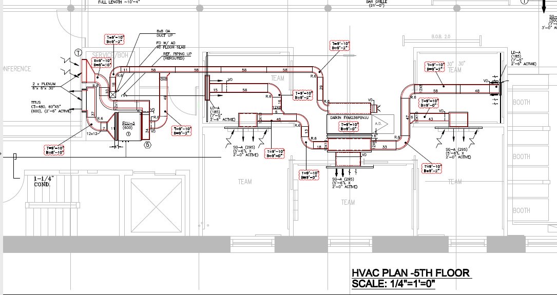
Hvac Drawing at Explore collection of Hvac Drawing

HVAC Plans by Raymond Alberga at Ventilation design

HVAC Plans by Raymond Alberga at
![]()
Silicon Engineering Consultants Limited New Zealand Mechanical

AutoCAD Tutorial HVAC Drawing Villa In Dubai AutoCAD HVAC How to

A complete guide to HVAC drawings and blueprints
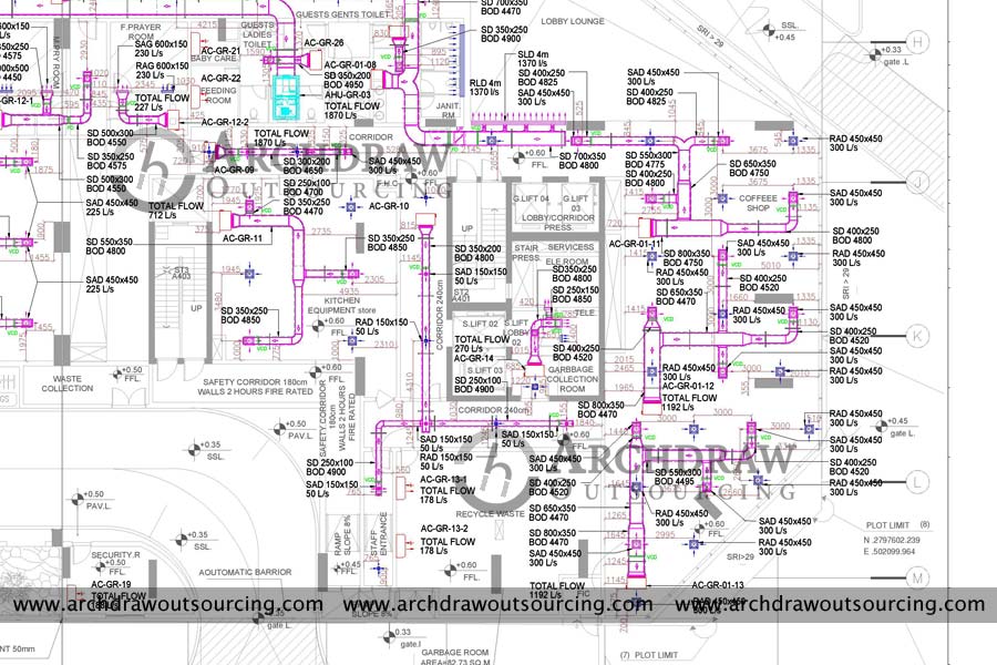
Hvac Drawings
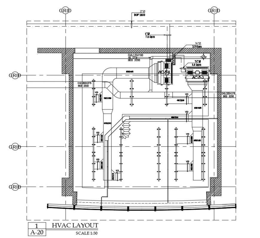
HVAC layout 2d cad drawing of autocad file Cadbull
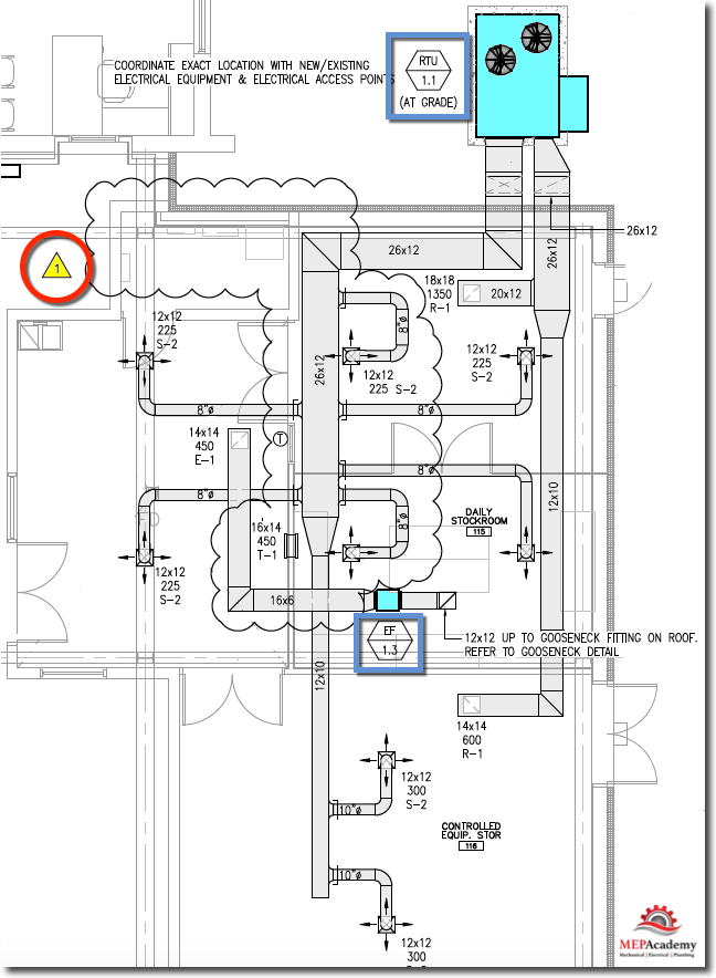
HVAC Mechanical Drawings MEP Academy
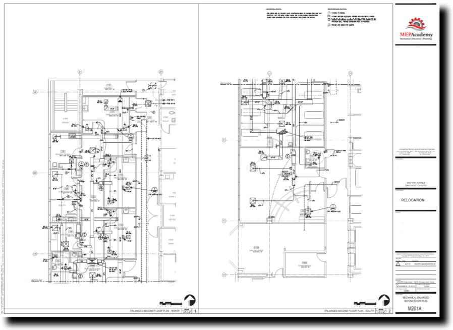
HVAC Mechanical Drawings MEP Academy
Drawings And General Provisions Of The Contract, Including General And Supplementary Conditions And Division 01 Specification Sections, Apply To This Section.
They Provide Crucial Information To Various Stakeholders Including:
Web Like Any Other Floor Plan Or Architectural Plan, An Hvac Plan Refers To The 2D Or 3D Representation Of All The Materials Or Equipment Needed By A Special Engineer To Create, Set Up, And Maintain The Heating And Cooling System Of Any Other Building.
Grille And Diffuser Quantity And Location.
Related Post: