Fillet Symbol In Engineering Drawing
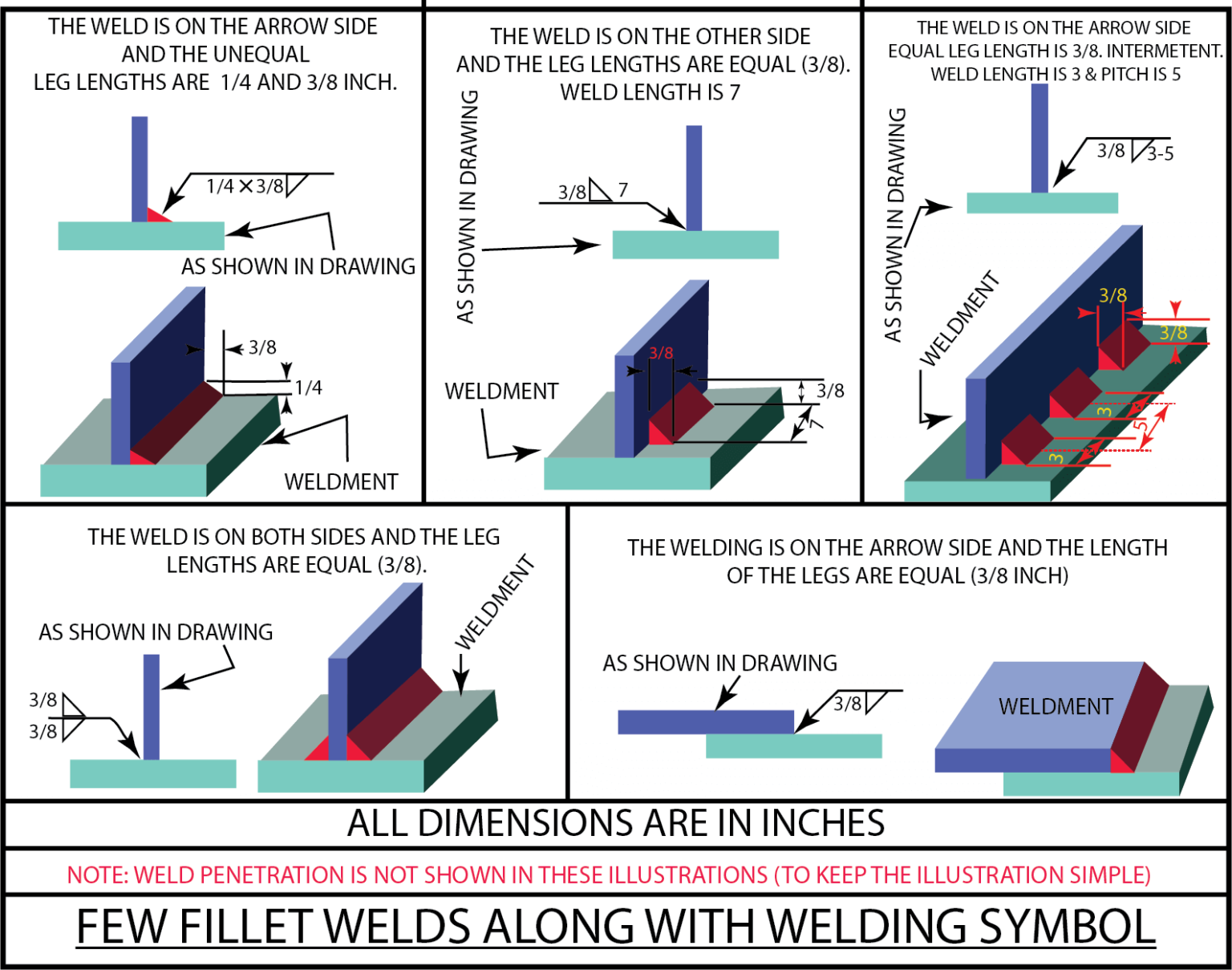
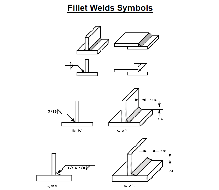
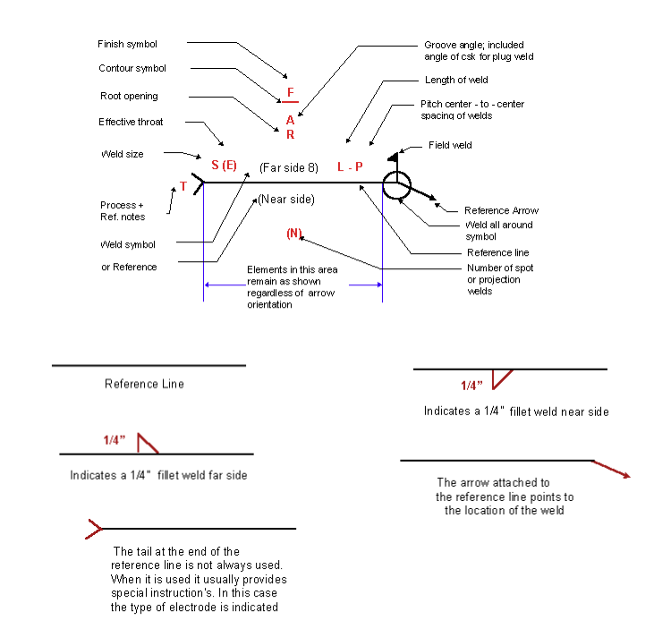
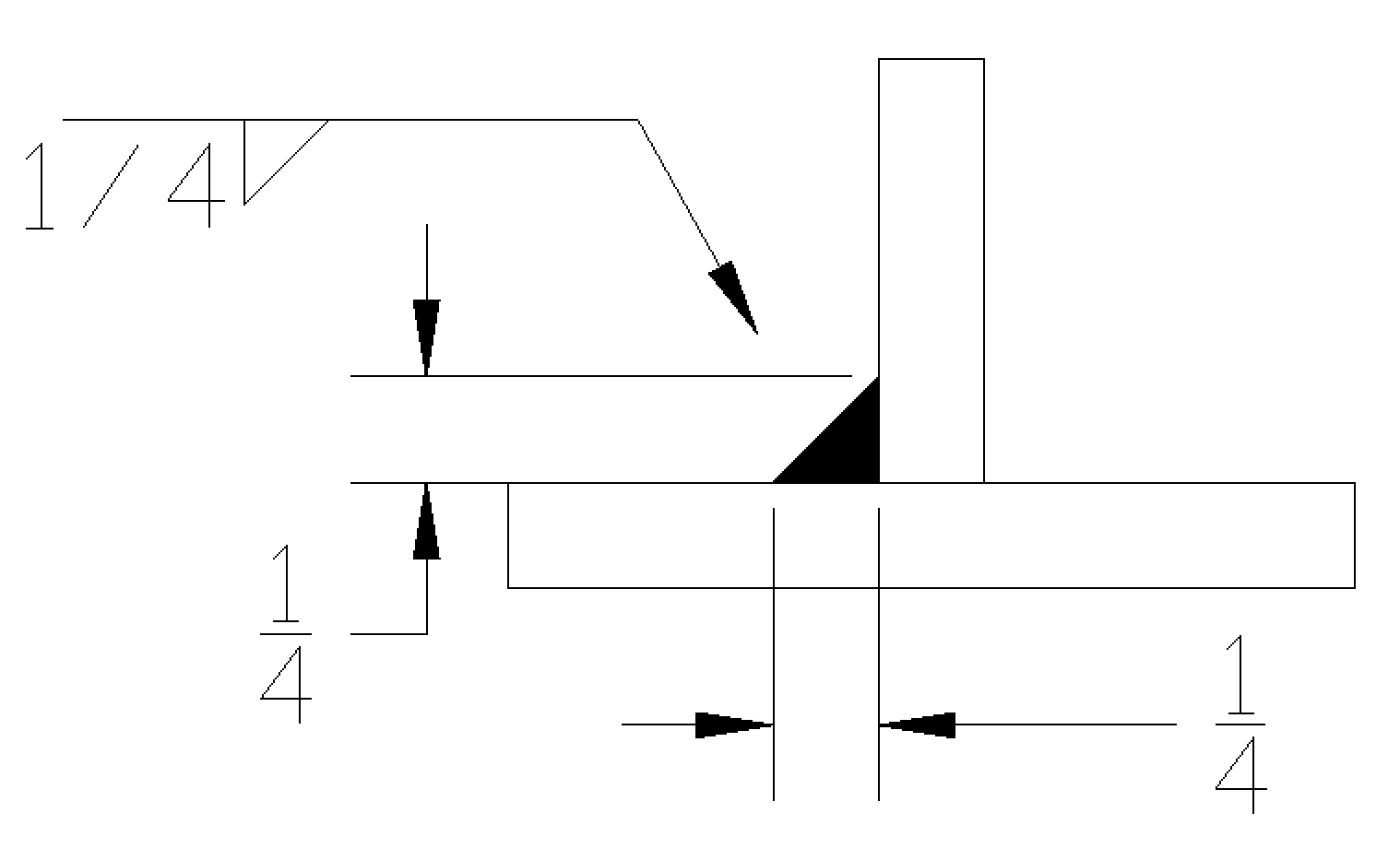
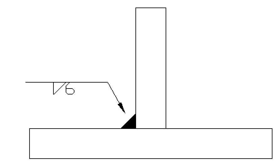
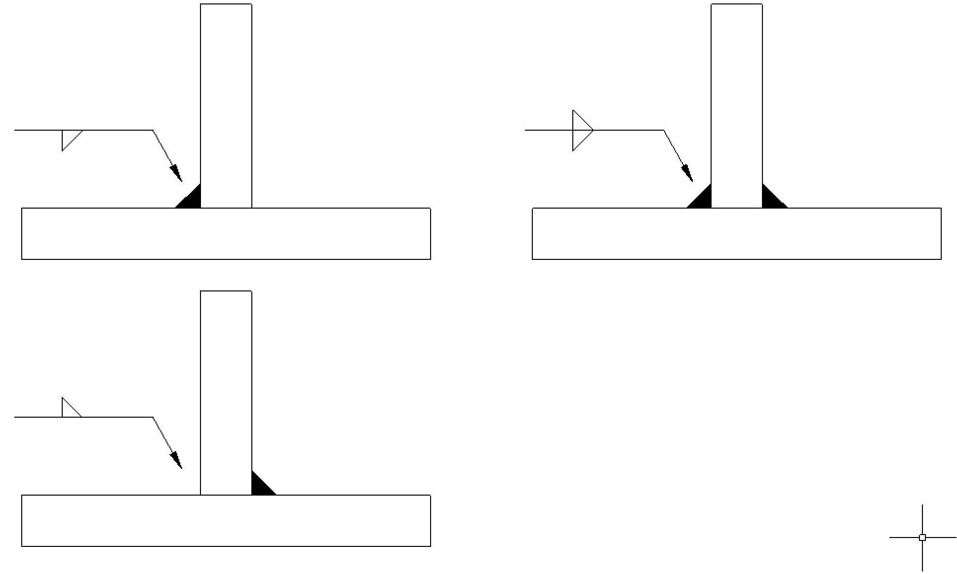
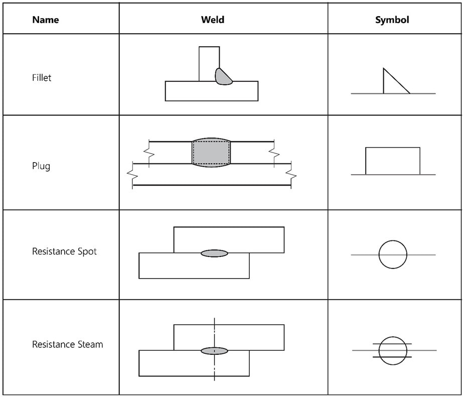
Fillet Symbol In Engineering Drawing - A fillet is indicated on a drawing in the same way as a round, illustrated in figure 2, with a dimension that includes the radius symbol and radius length. Fillets and rounds are specified using the “radius” symbol, “r”. Web welding symbols and drawings are essential for learning and understanding the correct way of welding. Web the fillet weld symbol is a right triangle placed on the reference line with the perpendicular leg always on the left. The vertical side of this triangle showing the fillet weld symbol is always placed on the left side of the drawing reader/ viewer as shown in the below figure. Web the fillet weld symbol can be represented with an arrow pointing up or down, indicating the location of the weld, either above or below the reference line. This weld is used when the joint has two members coming together to form an intersection of commonly 90 degrees. Fillet welds are one of the most common weld types in the industry. The following weld symbols are supported in iso: It is applicable to both metal fusion welding and resistance welding. Generally, but not in all cases, fillet welds are of equal legs. Engineering drawing symbols play a vital role in communication among engineers and other stakeholders involved in the design and construction process. This list includes abbreviations common to the vocabulary of people who work with engineering drawings in the manufacture and inspection of parts and assemblies. These welds can. Are used to give details about the weld type, weld size, & other supportive information such as welding process, surface finish requirements, etc. These are a set of symbols that describe the weld, the weld leg size, as well as giving processing and finishing information. A fillet weld symbol can be used with an arrow side. A fillet is indicated. Web in engineering drawings, fillets and rounds are typically specified using dimensional tolerances and geometrical tolerance symbols. A fillet weld symbol can be used with an arrow. Fillets and rounds are specified using the “radius” symbol, “r”. A fillet weld symbol can be used with an arrow side. Gb/t 5185 designation of metal welding and brazing methods in drawings; Learn more about fillets and rounds in the video below: You can see different fillet, plug, spot, and many other kinds of weld types. The weld symbol always includes. Web the fillet weld symbol can be represented with an arrow pointing up or down, indicating the location of the weld, either above or below the reference line. Figure 8 gives. Web drawing of weld symbols. Generally, but not in all cases, fillet welds are of equal legs. When identification of the weld process is required as part of the weld symbol the relevant weld process code is listed in bs en iso 4063. Web we notice welding symbols in fabrication & engineering drawings where lines and special geometrical shapes such. Figure 8 gives examples of symbols used in different standards. The following weld symbols are supported in iso: These welds can be applied on varying angles but this would be the most prominent. Fillet welds are one of the most common weld types in the industry. This weld is used when the joint has two members coming together to form. Web drawing of weld symbols. Gb/t 5185 designation of metal welding and brazing methods in drawings; Web engineering drawing abbreviations and symbols are used to communicate and detail the characteristics of an engineering drawing. Web what are the most commonly used engineering drawing symbols and their meanings? Web the weld_symbol_standard configuration option in the detail module enables you to set. It is applicable to both metal fusion welding and resistance welding. Web the most important symbols that you do have to memorize are the fillet weld symbol and the groove weld symbol. An interior or exterior corner, with an angle or type of bevel, is called a chamfer. The aws defines a fillet weld as: These are a set of. The radius value is given next to the symbol. The weld symbol always includes. The aws defines a fillet weld as: • grooved—square, bevel, v, u, and j. Engineering drawing symbols play a vital role in communication among engineers and other stakeholders involved in the design and construction process. Engineering drawing symbols play a vital role in communication among engineers and other stakeholders involved in the design and construction process. Web basic weld symbols. Web engineering drawing abbreviations and symbols are used to communicate and detail the characteristics of an engineering drawing. A fillet is indicated on a drawing in the same way as a round, illustrated in figure. Web basic weld symbols. You can see different fillet, plug, spot, and many other kinds of weld types. These welds can be applied on varying angles but this would be the most prominent. Web what are the most commonly used engineering drawing symbols and their meanings? Web welding symbols and drawings are essential for learning and understanding the correct way of welding. Web in mechanical engineering, a fillet is a rounding of an interior or exterior corner of a part designed in cad. These are a set of symbols that describe the weld, the weld leg size, as well as giving processing and finishing information. It may also be present on both sides of the reference line, in which case it is called a double fillet weld. Are used to give details about the weld type, weld size, & other supportive information such as welding process, surface finish requirements, etc. It is applicable to both metal fusion welding and resistance welding. Web the most important symbols that you do have to memorize are the fillet weld symbol and the groove weld symbol. Gb/t 5185 designation of metal welding and brazing methods in drawings; A fillet weld symbol can be used with an arrow. Web the fillet weld symbol can be represented with an arrow pointing up or down, indicating the location of the weld, either above or below the reference line. Web drawing of weld symbols. Web a fillet weld symbol can be used with an arrow side (below reference line) other side (above reference line) significance or on both sides (both sides of the reference line.) when a fillet weld is required on both sides.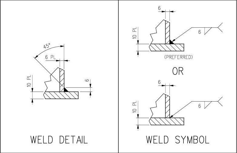
Dimensioning of welds Engineering Drawing Basics
![[SOLVED] In engineering drawing, the welding symbol used for fillet](https://storage.googleapis.com/tb-img/production/20/08/weld symbol1.PNG)
[SOLVED] In engineering drawing, the welding symbol used for fillet
Welding Symbols Guide to Reading Weld Symbols
Understanding the Welding Symbols in Engineering Drawings Safe Work

Engineering Drawing Weld Symbols
Understanding the Welding Symbols in Engineering Drawings Safe Work
Fillet Weld Symbols Interpretation of Metal Fab Drawings
Fillet Weld Symbols On Drawings
1.6 Fillet Weld Symbols Workforce LibreTexts
Welding Symbols Chart An Explanation of the Basics (with Pictures
Different Types Of Basic Weld Symbols Make Up The Fabrication Or Engineering Drawings.
This Standard Outlines The Method Of Presenting Welding Symbols.
These Welds Can Be Applied On Varying Angles But This Would Be The Most Prominent.
Fillets And Rounds Are Specified Using The “Radius” Symbol, “R”.
Related Post: