Engineering Drawing Types
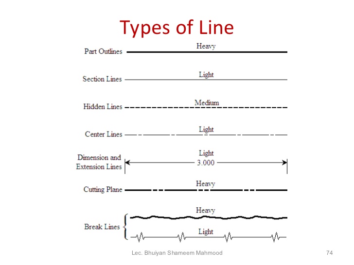
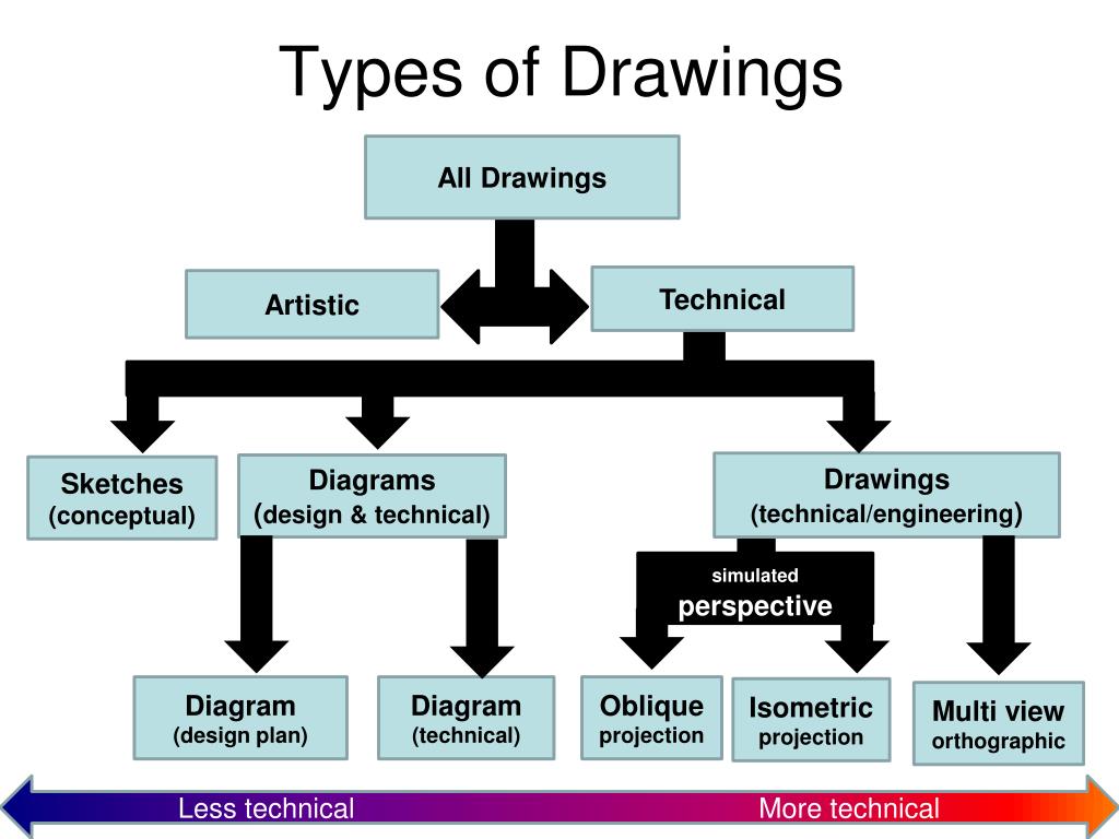
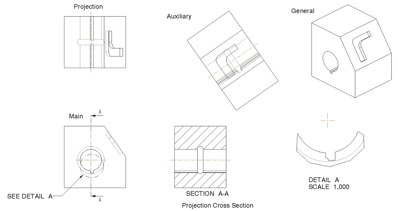
Engineering Drawing Types - Web main principles of creating multiview projections. Engineering drawing and related documentation practices. Usually, a number of drawings are necessary to completely specify even a simple component. Web the purpose of this guide is to give you the basics of engineering sketching and drawing. Web we will now discuss various types of engineering drawings or cad drawing views including: Web following are the different types of lines used in engineering drawing: What the difference is between counterbore and countersink holes. Web read about different types of drawing projection methods, and learn about the most important ones for engineering drawing creation. Orthographic projection, axonometric projection, sectional views, auxiliary views, detailed views, broken views and exploded view. More usually, the type of material is indicated elsewhere on the drawing, making the use of different types of cross. Web there are two common methods of engineering drawing: “drawing” usually means using drawing instruments, from compasses to computers to bring precision to the drawings. Web the following are the different types of views often used in engineering drawing: Web main principles of creating multiview projections. Basically, this type of drawing aims at clearly capturing all the geometric features of. Methods of making engineering drawing. The different types of holes used in machining. A subcategory of technical drawings is an engineering drawing, which we can define as engineering drawing as a graphical representation with the goal to convey all of the information required to manufacture a product or a component. How each type of hole is used in engineering. Engineering. Web some specialised and related degrees are: Here’s a look at some of the most common types of engineering drawings: In almost all objects, three views standard drawing views are adequate to describe it. What the difference is between counterbore and countersink holes. If the isometric drawing can show all details and all dimensions on one drawing, it is ideal. “drawing” usually means using drawing instruments, from compasses to computers to bring precision to the drawings. The glass box projections produced six views: These drawings show how multiple parts fit together to form a complete unit. Engineering drawings come in various types, each serving a unique purpose in the design and manufacturing process. However, the most common views are the. This makes understanding the drawings simple with little to no personal interpretation possibilities. Web there are two common methods of engineering drawing: Usually, a number of drawings are necessary to completely specify even a simple component. Web read about different types of drawing projection methods, and learn about the most important ones for engineering drawing creation. The different types of. This makes understanding the drawings simple with little to no personal interpretation possibilities. Web an engineering drawing is a type of technical drawing that is used to convey information about an object. Web an engineering drawing (also named as mechanical drawing, manufacturing blueprints, drawings, dimensional prints, and more) refers to one of the technical drawings, which helps to define engineering. Web following are the different types of lines used in engineering drawing: Engineering drawing and related documentation practices. Orthographic projection, axonometric projection, sectional views, auxiliary views, detailed views, broken views and exploded view. Isometric view (dimetric and trimetric view) orthographic view (front, side, top, bottom and back views) section view. Drawing boards, paper, rulers, calipers, and round gauges are essential. More usually, the type of material is indicated elsewhere on the drawing, making the use of different types of cross. Web the purpose of this guide is to give you the basics of engineering sketching and drawing. The main components of an engineering drawing are materials, construction techniques, and operational details. Web there are two common methods of engineering drawing:. Web 1.4 types of engineering drawing: The main components of an engineering drawing are materials, construction techniques, and operational details. Methods of making engineering drawing. The glass box projections produced six views: A common use is to specify the geometry necessary for the construction of a component and is called a detail drawing. Web dear engineer's, i'm reaching out to seek your expertise on a challenge i've encountered in interpreting certain engineering drawings. So let’s look at the different line and view types you will come across in. Most engineering projects start as drawings that convey details about an engineering or construction project. We will treat “sketching” and “drawing” as one. This is. This is a complete guide to the types of holes found in machining. “drawing” usually means using drawing instruments, from compasses to computers to bring precision to the drawings. Methods of making engineering drawing. Engineering graphics is used in the design process for visualization, communication, and documentation. A common use is to specify the geometry necessary for the construction of a component and is called a detail drawing. Web engineering working drawings basics. 2.3 comparison between traditional and digital methods. The symbols used for each hole and how they are shown on engineering drawings. Here’s a look at some of the most common types of engineering drawings: In almost all objects, three views standard drawing views are adequate to describe it. What the difference is between counterbore and countersink holes. Drawing boards, paper, rulers, calipers, and round gauges are essential tools for manual drawing. Test your knowledge with multiple choice flashcards. This makes understanding the drawings simple with little to no personal interpretation possibilities. However, the most common views are the six mutually perpendicular views that are produced by. So let’s look at the different line and view types you will come across in.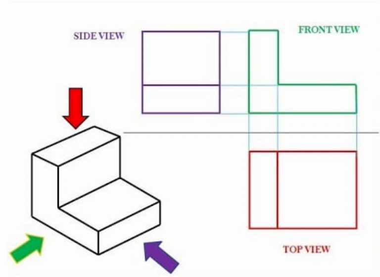
Engineering Drawing Views & Basics Explained Fractory
Engineering Drawing 8 Tips to Improve Engineering Drawing Skills

?What do you know about the engineering drawing « Ali's Engineering Design
PPT Technical Drawing PowerPoint Presentation, free download ID6696052

10 Different Types of Lines Used In Engineering Drawing

Mechanical Engineering Drawing and Design, Everything You Need To Know

6 types of engineering drawings
Engineering Drawings
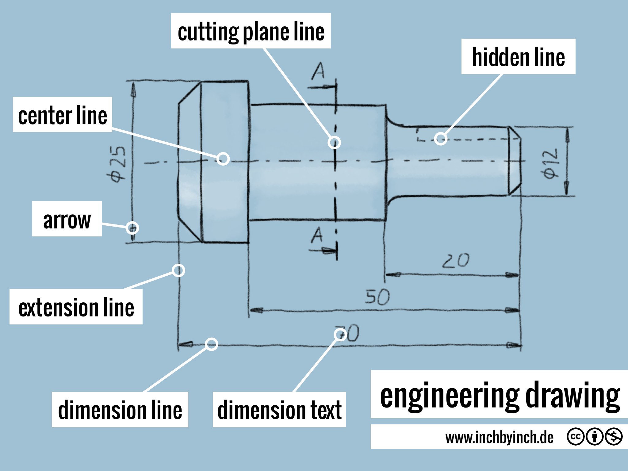
Different Types Of Engineering Drawings

Types Of Dimensions In Engineering Drawing at GetDrawings Free download
Engineering Drawing And Related Documentation Practices.
Engineering Drawings Come In Various Types, Each Serving A Unique Purpose In The Design And Manufacturing Process.
Web An Engineering Drawing (Also Named As Mechanical Drawing, Manufacturing Blueprints, Drawings, Dimensional Prints, And More) Refers To One Of The Technical Drawings, Which Helps To Define Engineering Products’ Requirements.
Web The Following Are The Different Types Of Views Often Used In Engineering Drawing:
Related Post: