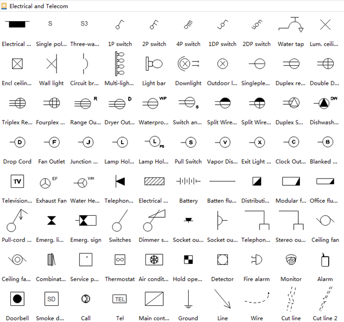
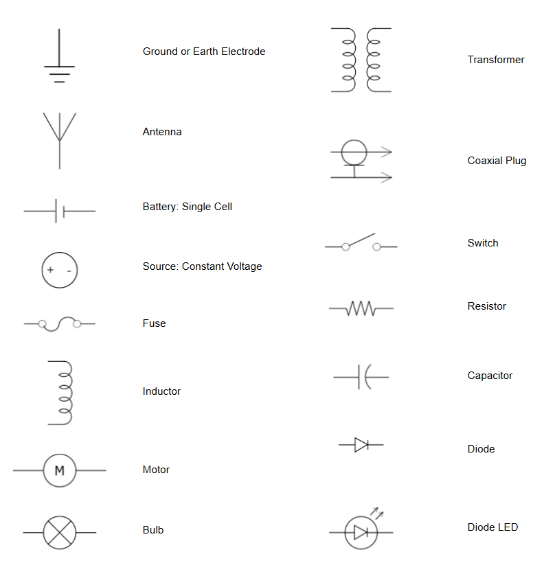
Electrical Schematic Drawing Symbols
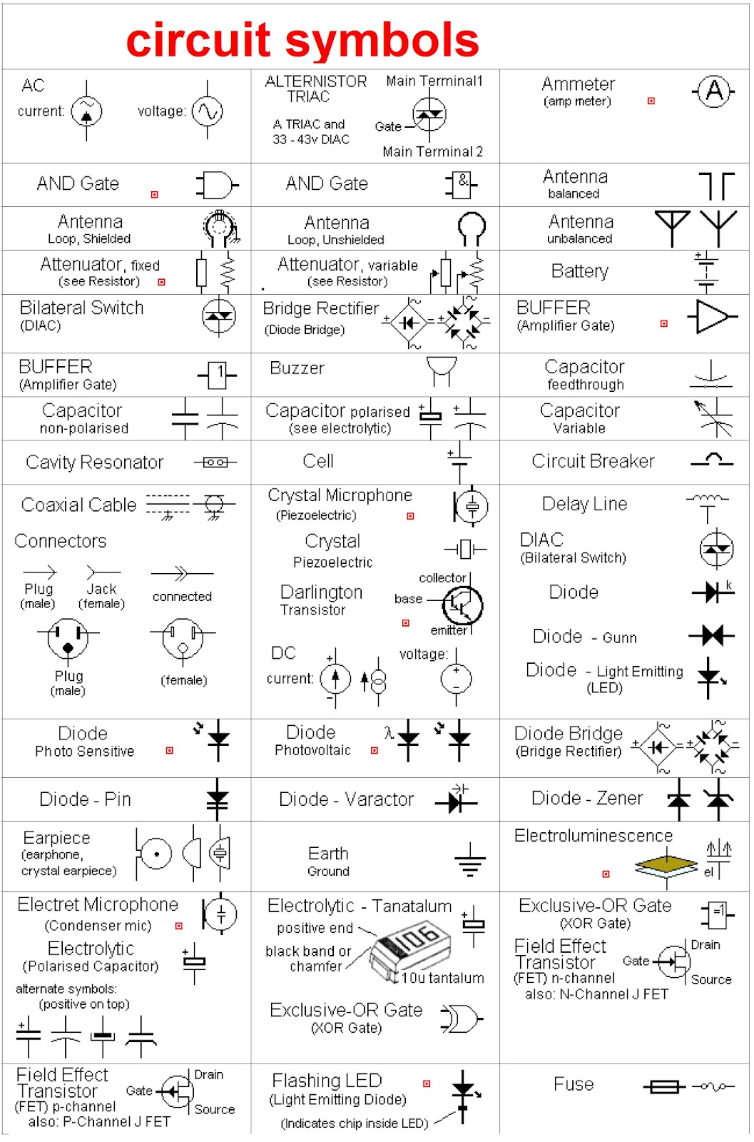
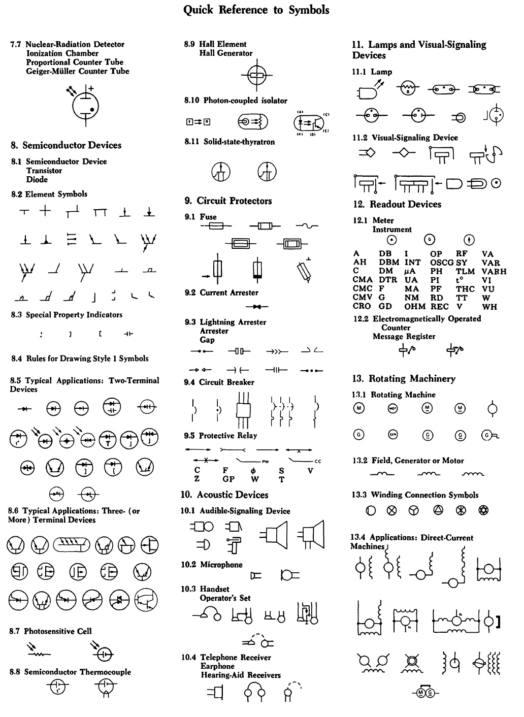
Electrical Schematic Drawing Symbols - Web basic electrical and electronic graphical symbols called schematic symbols are commonly used within circuit diagrams, schematics and computer aided drawing packages to identify the position of individual components and elements within a circuit. Explore common symbols for resistors, capacitors, switches, transistors, and more. Web common circuit diagram symbols (us ansi symbols) an electronic symbol is a pictogram used to represent various electrical and electronic devices or functions, such as wires , batteries , resistors , and transistors , in a schematic diagram of an electrical or electronic circuit. In schematics, many components are also represented by a letter code, shown in. The ground symbol is used to indicate the connection to a reference point, typically the physical ground or earth. Web electrical symbols are small pictograms that are used, for the sake of ease, clarity, and simplicity, in electrical schematic diagrams. Web while there are hundreds of different symbols used in electrical schematics, some of the most commonly used ones include a straight line for a wire, a zigzag line for a resistor, and two parallel lines for a capacitor. Web learn about the different electrical circuit diagram symbols used to represent various components and connections in a circuit. October 8, 2020 by øyvind nydal dahl. Web electrical symbols and electronic circuit symbols are used for drawing schematic diagram. Web schematic symbols are graphical representations used in electrical circuits to represent various components and devices. This article gives some of the frequently used symbols for drawing the circuits. The symbols represent electrical and electronic components. Explore common symbols for resistors, capacitors, switches, transistors, and more. Web basic electrical and electronic graphical symbols called schematic symbols are commonly used within. Web electrical symbols and electronic circuit symbols are used for drawing schematic diagram. The ground symbol is used to indicate the connection to a reference point, typically the physical ground or earth. Explore common symbols for resistors, capacitors, switches, transistors, and more. What are the basic electrical symbols? Web iec 60617 contains graphical symbols for use in electrotechnical diagrams. Web learn about the different electrical circuit diagram symbols used to represent various components and connections in a circuit. Web electrical symbols and electronic circuit symbols are used for drawing schematic diagram. Web schematic symbols are graphical representations used in electrical circuits to represent various components and devices. This article gives some of the frequently used symbols for drawing the. The most fundamental of circuit components and symbols! Web some commonly used symbols in an electrical schematic symbols chart include: In schematics, many components are also represented by a letter code, shown in. Explore common symbols for resistors, capacitors, switches, transistors, and more. Web below are some important wiring diagram symbols to know: Create more than 280 types of diagrams effortlessly. The resistor symbol represents each light bulb. Represented by two parallel lines. Web common circuit diagram symbols (us ansi symbols) an electronic symbol is a pictogram used to represent various electrical and electronic devices or functions, such as wires , batteries , resistors , and transistors , in a schematic diagram of. Represented by a zigzag line. To be able to read schematics you must know the basic schematic symbols used in electronics. One of the key benefits of using electrical schematic symbols is their universality. By learning these symbols, beginners can quickly identify and interpret the different. Web iec 60617 contains graphical symbols for use in electrotechnical diagrams. Each physical component (i.e resistor , capacitor , transistor ) has a unique schematic symbol. The ground symbol is used to indicate the connection to a reference point, typically the physical ground or earth. Web schematic symbols are graphical representations used in electrical circuits to represent various components and devices. Wiring diagrams use simplified symbols to represent switches, lights, outlets,. The database is the official source of. October 8, 2020 by øyvind nydal dahl. Web basic electrical and electronic graphical symbols called schematic symbols are commonly used within circuit diagrams, schematics and computer aided drawing packages to identify the position of individual components and elements within a circuit. Web our circuit diagram symbol library is schematic and includes many icons. Here is the wiring symbol legend, which is a detailed documentation of common symbols that are used in wiring diagrams, home wiring plans, and electrical wiring blueprints. Web electrical symbols and electronic circuit symbols are used for drawing schematic diagram. Web basic electrical and electronic graphical symbols called schematic symbols are commonly used within circuit diagrams, schematics and computer aided. The symbols represent electrical and electronic components. The ground symbol is used to indicate the connection to a reference point, typically the physical ground or earth. Transitioning into practical applications, we’ll spotlight different forms of common electrical symbols frequently encountered in construction drawings, providing insights into their widespread usage and interpretation. This article gives some of the frequently used symbols. These symbols help electrical engineers, technicians, and hobbyists understand the layout and functioning of a circuit without having to study its detailed schematic diagram. What are the basic electrical symbols? Web basic electrical and electronic graphical symbols called schematic symbols are commonly used within circuit diagrams, schematics and computer aided drawing packages to identify the position of individual components and elements within a circuit. Electrical symbols or electronic circuits are virtually represented by circuit diagrams. Web these symbols provide a standardized representation of components such as resistors, capacitors, inductors, diodes, transistors, switches, and more. Web to start developing your schematic reading abilities, it’s important to memorize the most common schematic symbols. Web the most common schematic symbols used in electronics. Here is the wiring symbol legend, which is a detailed documentation of common symbols that are used in wiring diagrams, home wiring plans, and electrical wiring blueprints. These are the most basic electrical diagram symbols, which can represent simple circuits. 2 or 3) of the previously published iec 60617 have been incorporated into this database that currently includes some 1900 symbols. The ground symbol is used to indicate the connection to a reference point, typically the physical ground or earth. Represented by a zigzag line. There are some standard symbols to represent the components in a circuits. Web our circuit diagram symbol library is schematic and includes many icons commonly used by engineers. Web while there are hundreds of different symbols used in electrical schematics, some of the most commonly used ones include a straight line for a wire, a zigzag line for a resistor, and two parallel lines for a capacitor. Transitioning into practical applications, we’ll spotlight different forms of common electrical symbols frequently encountered in construction drawings, providing insights into their widespread usage and interpretation.
How to Read a Schematic SparkFun Learn
Electronic circuit, componnent data, lesson and etc…. circuit symbols

Printable Electrical Schematic Symbols Chart Pdf
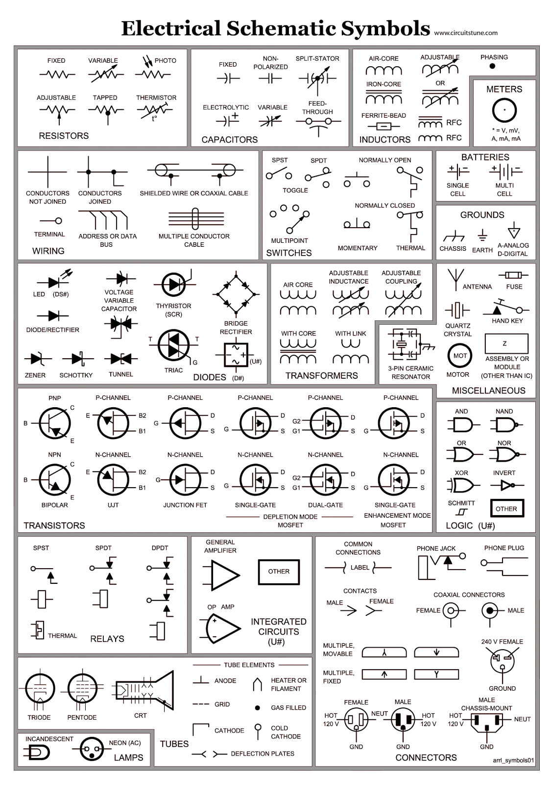
Electrical Schematic Symbols CircuitsTune
How to Read and Interpret Electrical Shop Drawings Part Two

Electrical Schematic Symbols CircuitsTune

ELECTRICAL LEGEND SINGLE LINE & SCHEMATIC SYMBOLS CAD Block And
Electrical Symbols Electrical Drawing Symbols Electrical Academia
Electrical Drawing Symbols at Explore collection
Electrical Symbols Try Our Electrical Symbol Software Free
Web Iec 60617 Contains Graphical Symbols For Use In Electrotechnical Diagrams.
The Connecting Lines Are Used To Connect The Symbols.
To Start With, It’s Usually Enough To Know The Battery, Resistor, Capacitor, Transistor, Diode, Led,.
The Resistor Symbol Represents Each Light Bulb.
Related Post: