Draw The Shear And Moment Diagrams For The Simplysupported Beam
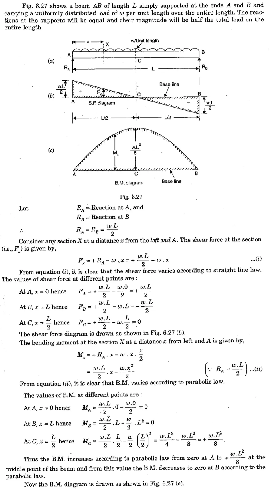
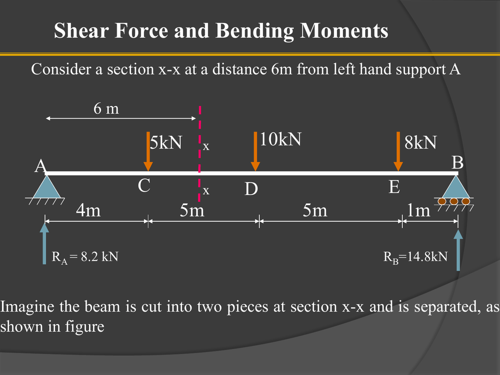
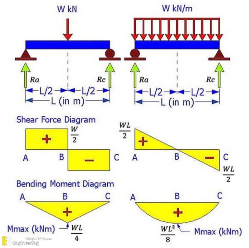
Draw The Shear And Moment Diagrams For The Simplysupported Beam - You will have a robust system of analysis that allows you to confidently tackle the analysis of. There are 3 steps to solve this one. M m a x = 1 / 8 ⋅ q ⋅ l 2. Neglect the weight of the beam. By laurin ernst updated december 30, 2022. The solution for \(v(x)\) and \(m(x)\) takes the following steps: In this video, shear stress and bending. Web draw the shear and moment diagrams for the simply supported beam. 90k views 3 years ago statics. Web figures 1 through 32 provide a series of shear and moment diagrams with accompanying formulas for design of beams under various static loading conditions. A) find the shear force v and bending moment in section c1, c2. You will have a robust system of analysis that allows you to confidently tackle the analysis of. [latex]\delta m=\int v (x)dx [/latex] (equation 6.2) equation 6.2 states that the change in moment equals the area under the shear diagram. 90k views 3 years ago statics. There are. Web you will be fully competent in drawing shear force and bending moment diagrams for statically determinate beams and frames. Web the equation also suggests that the slope of the moment diagram at a particular point is equal to the shear force at that same point. M ( x) = 1 / 2 ⋅ q ⋅ x ⋅ ( l. 57k views 3 years ago shear force and bending moment diagram solved problems. M m a x = 1 / 8 ⋅ q ⋅ l 2. V a = − v b = 1 / 2 ⋅ q ⋅ l. The support reactions a and c have been computed, and their values are shown in fig. Web you will be. And (2) draw the shear force and bending moment diagrams. As we used fe programs to calculate the bending moments, shear forces and deflections of structures in last tutorials, we are going a step back now to the very basics of structural engineering and do hand calculations. 291k views 2 years ago engineering statics. Learn to draw shear force and. As we used fe programs to calculate the bending moments, shear forces and deflections of structures in last tutorials, we are going a step back now to the very basics of structural engineering and do hand calculations. Equation 6.1 suggests the following expression: Simply supported beam with uniformly varying load (uvl). 57k views 3 years ago shear force and bending. A) find the shear force v and bending moment in section c1, c2. Web you will be fully competent in drawing shear force and bending moment diagrams for statically determinate beams and frames. Shear force and bending moment values are calculated at supports and at points where load varies. Neglect the weight of the beam. (1) derive the shear and. Web shear force and bending moment diagram for a simply supported beam are as follows. 100% (2 ratings) share share. Simply supported beam with uniformly varying load (uvl). Web shear force and bending moment | simply supported beam | english | point load | udl #somin this video i discussed about shear force and bending moment diagr. The support reactions. [latex]\delta m=\int v (x)dx [/latex] (equation 6.2) equation 6.2 states that the change in moment equals the area under the shear diagram. Web how to draw shear and moment diagram for a simply supported beam? 50 kn 50 kn 50 kn 50 kn a b 2m 3m 4m 4m +3m a simple supported beam ab is under two concentrated loads. In this video i find the end. Web the weight of the beam is ignored. Web how to draw shear and moment diagram for a simply supported beam? By laurin ernst updated december 30, 2022. 170k views 5 years ago bending moment diagram & shear force diagram (bmd & sfd) this video explains how to draw shear. Simply supported beam with uniformly distributed load (udl) & point load. Learn to draw shear force and moment diagrams using 2 methods, step by step. Web bending moment and shear force diagram | simply supported beam with uniformly distributed line load (udl). The solution for \(v(x)\) and \(m(x)\) takes the following steps: 57k views 3 years ago shear force and. Web bending moment and shear force diagram | simply supported beam with uniformly distributed line load (udl). A) find the shear force v and bending moment in section c1, c2. Learn to draw shear force and moment diagrams using 2 methods, step by step. Simply supported beam with uniformly distributed load (udl) & point load. Web the weight of the beam is ignored. Taking moment of all the forces about poin. Web shear force and bending moment diagrams are analytical tools used in conjunction with structural analysis to help perform structural design by determining the value of shear forces and bending moments at a given point of a structural element such as a beam. Web figures 1 through 32 provide a series of shear and moment diagrams with accompanying formulas for design of beams under various static loading conditions. V a = − v b = 1 / 2 ⋅ q ⋅ l. Moment and shear hand calculation. 170k views 5 years ago bending moment diagram & shear force diagram (bmd & sfd) this video explains how to draw shear. The support reactions a and c have been computed, and their values are shown in fig. Shear force and bending moment values are calculated at supports and at points where load varies. Relationship between shear (v) and moment (m) diagrams and steel reinforcements in a simply supported and cantilever beam. We go through breaking a beam into segments, and then we. As we used fe programs to calculate the bending moments, shear forces and deflections of structures in last tutorials, we are going a step back now to the very basics of structural engineering and do hand calculations.
Shear force and bending moment diagrams for a simply supported beam

Shear Force and bending moment diagram for Simply supported Beam

Learn How To Draw Shear Force And Bending Moment Diagrams Engineering

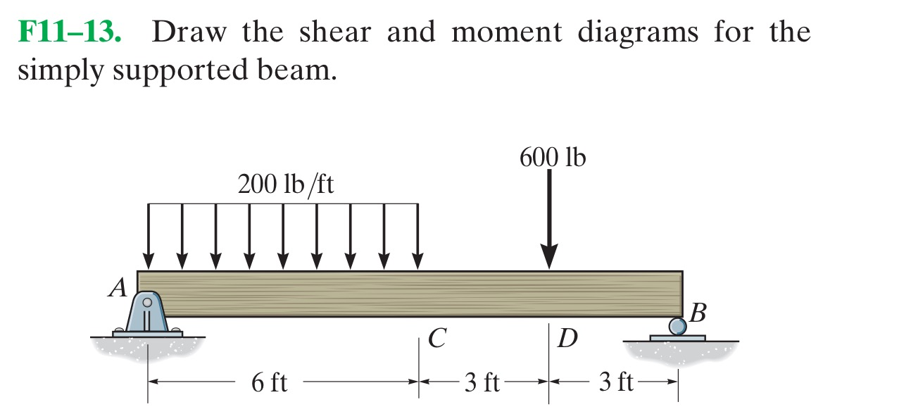
Solved Draw the shear and moment diagrams for the simply
Simply Supported UDL Beam Formulas Bending Moment Equations

How To Draw Shear Force And Bending Moment Diagram For Simply Supported

Solved Draw the shear and moment diagrams for the beam.

Brief Information About Shear Force And Bending Moment Diagrams

Shear and Moment Diagram Simply Supported Beam (Point Load) YouTube

SHEAR FORCE AND BENDING MOMENT DIAGRAM FOR SIMPLY SUPPORTED BEAM WITH
The Solution For \(V(X)\) And \(M(X)\) Takes The Following Steps:
57K Views 3 Years Ago Shear Force And Bending Moment Diagram Solved Problems.
Web The Equation Also Suggests That The Slope Of The Moment Diagram At A Particular Point Is Equal To The Shear Force At That Same Point.
Web Shear Force And Bending Moment Diagram Of Simply Supported Beam Can Be Drawn By First Calculating Value Of Shear Force And Bending Moment.
Related Post: