Draw The Shear And Moment Diagram For The Beam
Draw The Shear And Moment Diagram For The Beam - To create the shear force diagram, we will use the following process. The shear force and bending moment diagrams are convenient visual references to the internal forces in a beam; Also, draw shear and moment diagrams, specifying values at all change of loading positions and at. Web the first step in calculating these quantities and their spatial variation consists of constructing shear and bending moment diagrams, \(v(x)\) and \(m(x)\), which are the internal shearing forces and bending moments induced in. This page will walk you through what shear forces and bending moments are, why they are useful, the procedure for drawing the diagrams and some other keys aspects as well. Web below is a simple example of what shear and moment diagrams look like, afterwards, the relation between the load on the beam and the diagrams will be discussed. 2.1k views 1 year ago chapter 6 (bending) by mechanics of materials r.c hibbeler (9th edition), complete solution by engr adnan. This is an example problem that will show you how to graphically draw a shear and moment diagram for a beam. Web you'll get a detailed solution from a subject matter expert that helps you learn core concepts. Web in order to construct shear and moment diagrams for a beam, first, determine the reactive forces and couple moments acting on the beam, and resolve all the forces into components acting perpendicular and parallel to the beam’s axis. In general the process goes like this:. In each problem, let x be the distance measured from left end of the beam. Internal forces in beams and frames, libretexts. Draw a free body diagram of the beam with global coordinates (x) calculate the reaction forces using equilibrium equations ( ∑ forces = 0 and ∑ moments = 0 ). [latex]\delta. Web shear force and bending moment diagrams are powerful graphical methods that are used to analyze a beam under loading. To create the shear force diagram, we will use the following process. Web by plotting these expressions to scale, obtain the shear force and bending moment diagrams for the beam. Draw a free body diagram of the beam with global. Draw out a free body diagram of the body horizontally. Web write equations for the shear v and bending moment m for any section of the beam in the interval ab. Web to create a shear and moment diagram, you will need to follow a few steps. [latex]\delta m=\int v (x)dx [/latex] (equation 6.2) equation 6.2 states that the change. 90k views 3 years ago statics. This page will walk you through what shear forces and bending moments are, why they are useful, the procedure for drawing the diagrams and some other keys aspects as well. Once these are determined, derive the shear and moment functions. Beam reactions, shear and moment (page 7 of 12) w l sym. Determine all. First, determine the external loads and reactions acting on the element. Solve for all external forces acting on the body. 20 kn 40 kn/m cl 150 kn m 8 m 3 m prob. Start at one end, (point a), of the beam and work toward the other end. 7.3k views 2 years ago statics. Then, calculate the shear and bending moment at various points using equations or diagrams. There are 4 steps to solve this one. The beginning, end, or change of a load pattern. In general the process goes like this:. This is an example problem that will show you how to graphically draw a shear and moment diagram for a beam. Web our calculator generates the reactions, shear force diagrams (sfd), bending moment diagrams (bmd), deflection, and stress of a cantilever beam or simply supported beam. Beam reactions, shear and moment (page 7 of 12) w l sym. Web shear force and bending moment diagrams are analytical tools used in conjunction with structural analysis to help perform structural design by determining. Then, calculate the shear and bending moment at various points using equations or diagrams. Web this video explains how to draw shear force diagram and bending moment diagram with easy steps for a simply supported beam loaded with a concentrated load. Once you have the reactions, draw your free body diagram and shear force diagram underneath the beam. This page. This problem has been solved! In particular, they identify the maximum values of v and m. Draw a free body diagram of the beam with global coordinates (x) calculate the reaction forces using equilibrium equations ( ∑ forces = 0 and ∑ moments = 0 ). Web draw the shear and moment diagrams for the beam (a) in terms of. The beginning, end, or change of a load pattern. Web to create a shear and moment diagram, you will need to follow a few steps. This page will walk you through what shear forces and bending moments are, why they are useful, the procedure for drawing the diagrams and some other keys aspects as well. Web write equations for the. The reactions shown on the diagram are determined from equilibrium equations as follows: The shear force and bending moment diagrams are convenient visual references to the internal forces in a beam; (9) 9 × 0 2 3 ∴ r = 9 kn. (b) set p = 800 lb, a = 5 ft, l = 12 ft. In general the process goes like this:. You'll get a detailed solution from a subject matter expert that helps you learn core concepts. Draw the shear and moment diagrams for the beam. Equation 6.1 suggests the following expression: Web shear force and bending moment diagrams are powerful graphical methods that are used to analyze a beam under loading. Once these are determined, derive the shear and moment functions. Beam reactions, shear and moment (page 7 of 12) w l sym. Internal forces in beams and frames, libretexts. Web the first step in calculating these quantities and their spatial variation consists of constructing shear and bending moment diagrams, \(v(x)\) and \(m(x)\), which are the internal shearing forces and bending moments induced in. Shear and moment diagrams and formulas are excerpted from the western woods use book, 4th edition, and are provided herein as a courtesy of. Divide the beam (of length l) into n segments. Start at one end, (point a), of the beam and work toward the other end.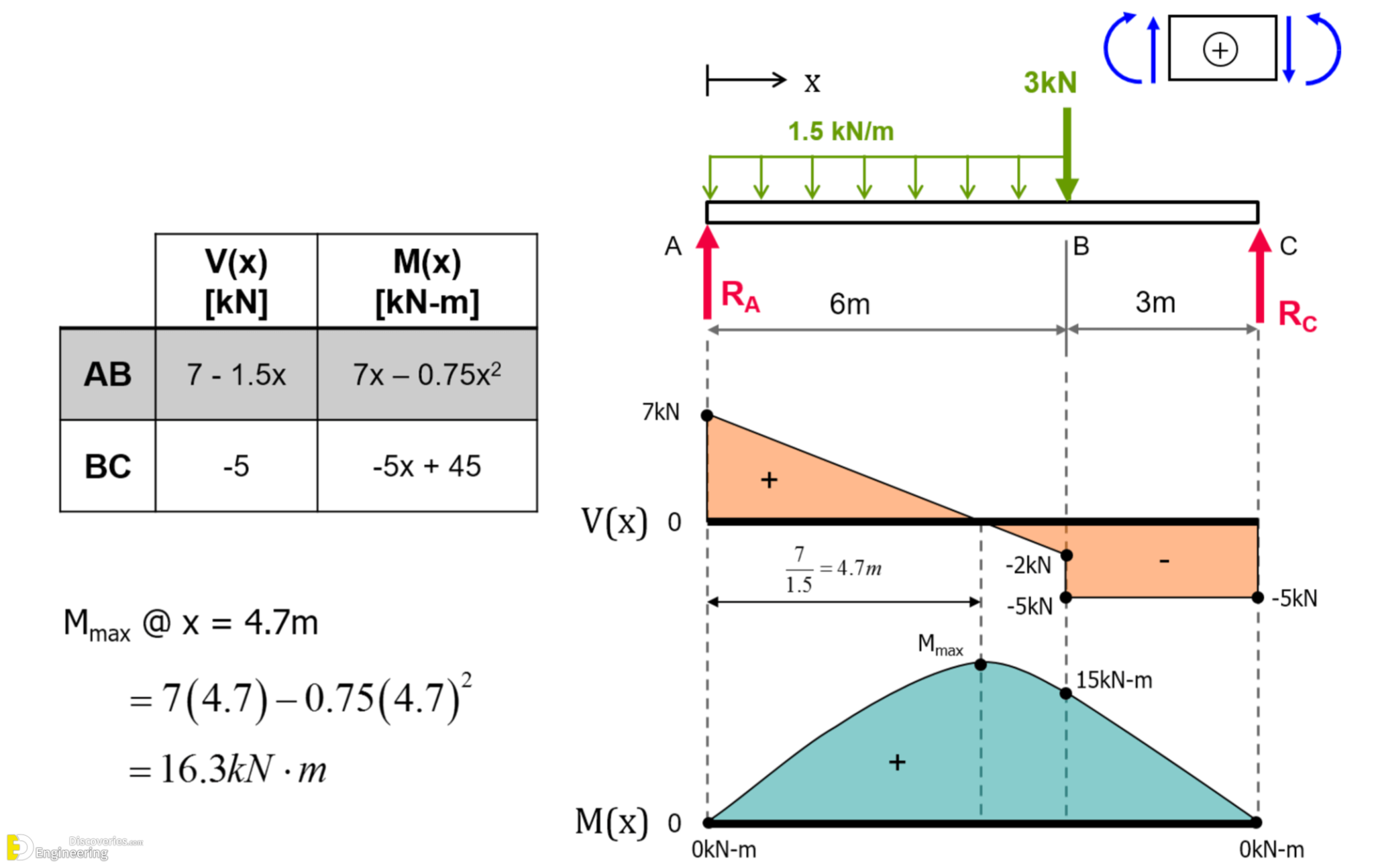
Learn How To Draw Shear Force And Bending Moment Diagrams Engineering

Solved Draw the shear and moment diagrams for the beam
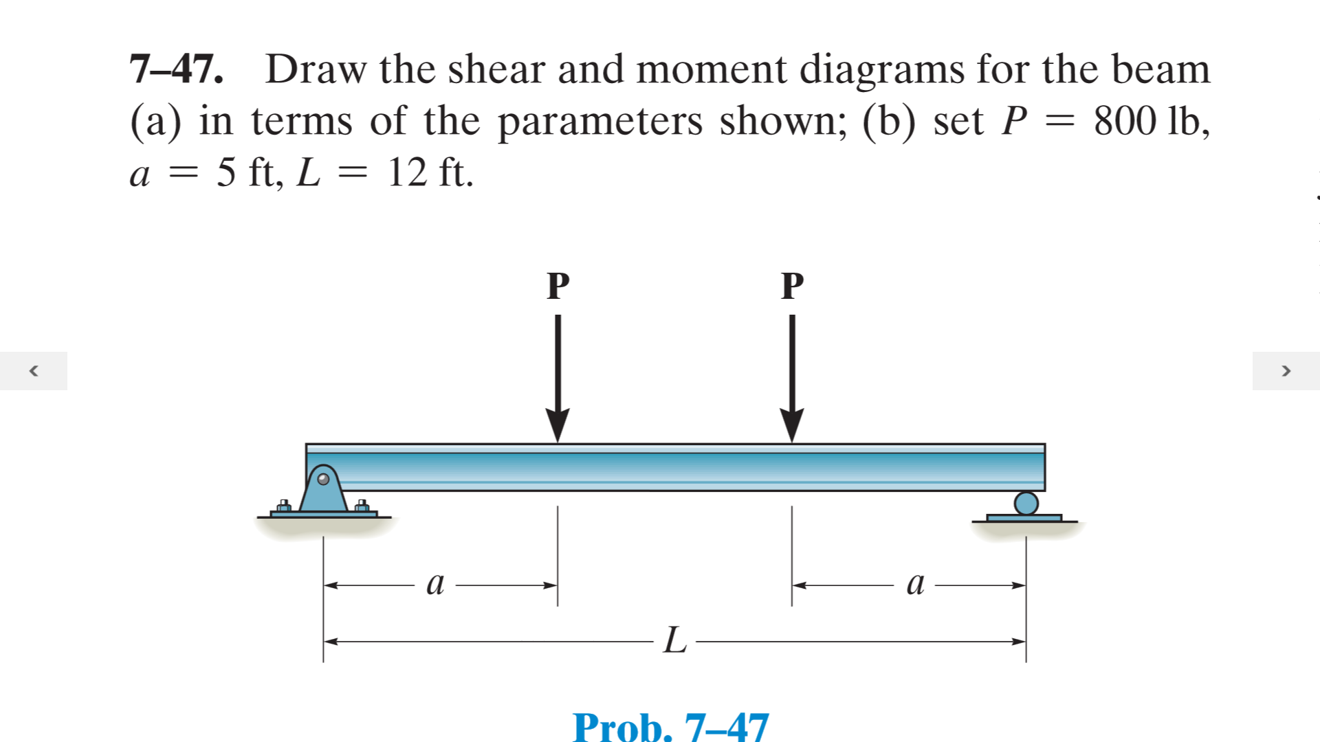
Solved Draw the shear and moment diagrams for the beam (a)
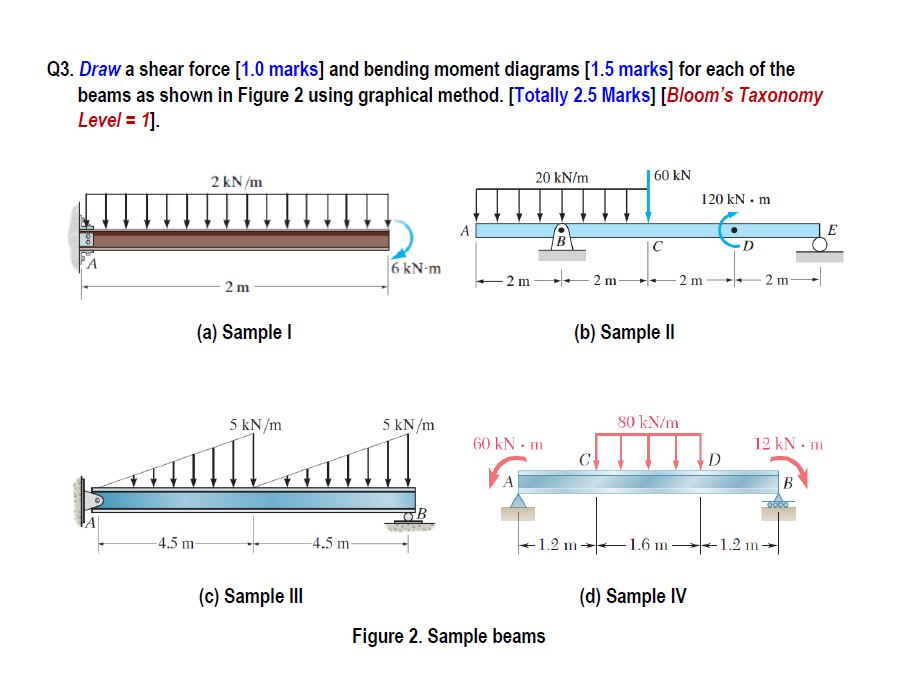
Shear and moment diagrams geekloki

Drawing Shear and Moment Diagrams for Beam YouTube

Solved Draw the shear and moment diagrams for the beam.
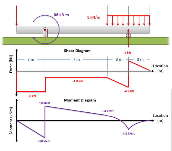
Mechanics Map Shear and Moment Diagrams
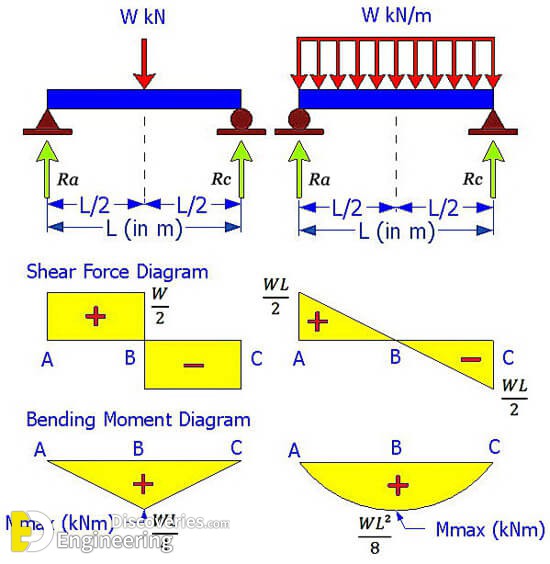
Learn How To Draw Shear Force And Bending Moment Diagrams Engineering

Learn How To Draw Shear Force And Bending Moment Diagrams Engineering
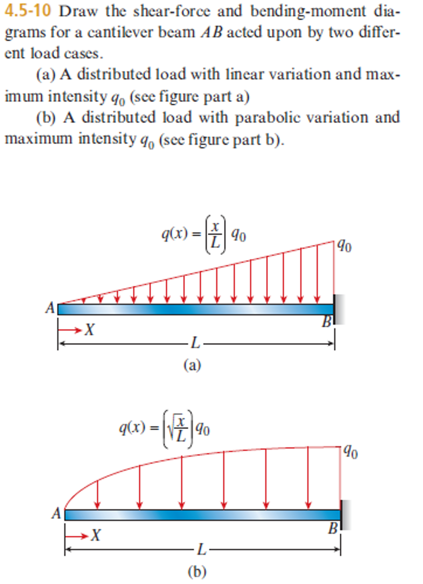
Shear force and bending moment diagrams for beams pdf
Web Write Equations For The Shear V And Bending Moment M For Any Section Of The Beam In The Interval Ab.
Draw Out A Free Body Diagram Of The Body Horizontally.
Determine All The Reactions On The Beam.
3 Algebraic Summation Of Coordinates Of These Three Moment Diagrams Will Produce The Final Moment Diagram.
Related Post: