Dimensioning In Engineering Drawing
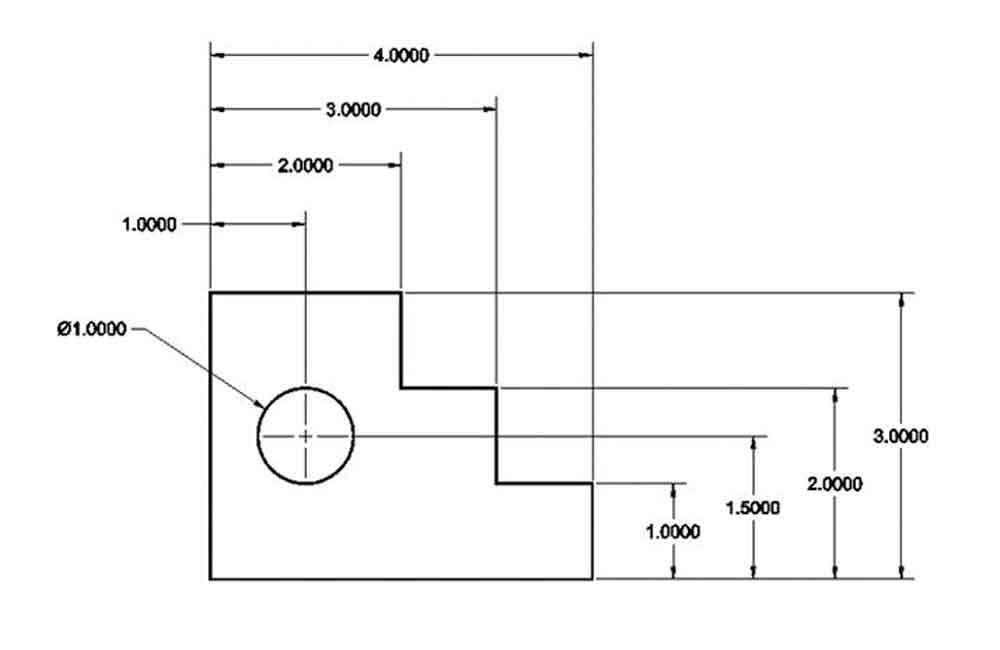
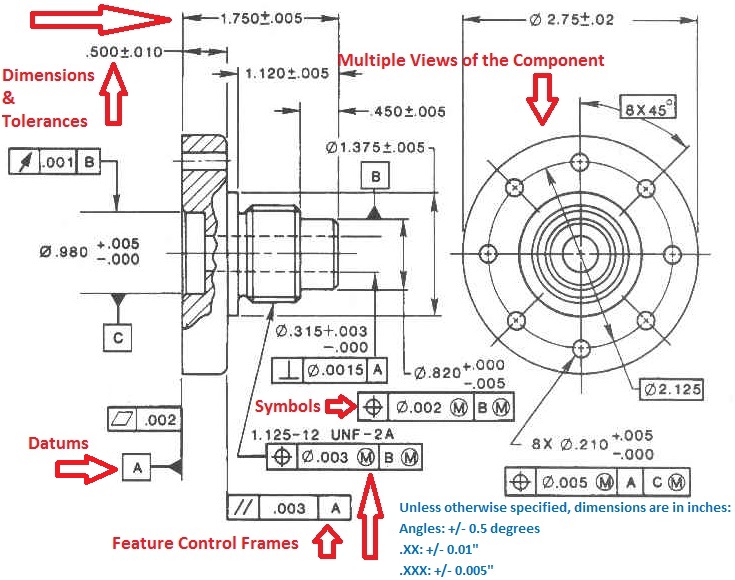
Dimensioning In Engineering Drawing - Engineering drawings and sketches need to display simplicity and uniformity, and they must be executed with speed. Dimensions in engineering drawings are numerical values indicated graphically in a proper unit of measurement on engineering drawing with lines, symbols, and notes. Before an object can be built, complete information about both the size and shape of the object must be available. Web essentially, dimensioning refers to the process of specifying the exact size, shape, and location of different parts and features on an engineering drawing. In other words, with the use of dimensioning technics on the engineering drawings, we define the physical boundaries of the component, like the size and location of the different features. Some methods of dimensioning a drawing can produce an accumulated error. Conventional parts (areas) abbreviations and symbols. 3.2 lines, angles, and dimensions. Proper use of gd&t can improve quality and reduce the time and cost of delivery. Using gd&t results in a more accurate design, larger tolerances for less important design features, and cost savings for manufacturing. The base is ½” x 1 ½” square. Web three principles of dimensioning must be followed: Before an object can be built, complete information about both the size and shape of the object must be available. In other words, with the use of dimensioning technics on the engineering drawings, we define the physical boundaries of the component, like the size. 3.2 lines, angles, and dimensions. 12k views 2 years ago #howtodraw #geometry. Web systems of dimensioning and tolerancing. Some methods of dimensioning a drawing can produce an accumulated error. Web essentially, dimensioning refers to the process of specifying the exact size, shape, and location of different parts and features on an engineering drawing. The angle begins as the midpoint of the 3” long dimension. While you may not be accustomed to reading dimensions from a technical drawing, you probably have had practice using dimensioning principles in your everyday life. Dimensions in engineering drawings are numerical values indicated graphically in a proper unit of measurement on engineering drawing with lines, symbols, and notes. Dimensioning. Learn the fundamental rules of dimensioning in engineering/architectural/structural drawings. The angle begins as the midpoint of the 3” long dimension. Parallels, running, chains, & combined amplitude. Web in this video, we are going to learn about dimensions in engineering drawing! 12k views 2 years ago #howtodraw #geometry. Web what is dimensioning in engineering drawing? The exact shape of the part or assembly is shown by the different views in the drawing sheet. Dimensions in engineering drawings are numerical values indicated graphically in a proper unit of measurement on engineering drawing with lines, symbols, and notes. Fundamentally, engineers design a part with perfect geometry in cad, but manufactured. The dimensions are 3” long, 2 1/8” wide, 1 5/8” high with a 45 angle ½” deep. Web systems of dimensioning and tolerancing. Correct values must be given. 12k views 2 years ago #howtodraw #geometry. Dimensions and notations must be placed on the sketch where they can be clearly and easily read. The base is ½” x 1 ½” square. Gd&t is a way of describing the dimensions and tolerances that’s different from traditional coordinate measurement plus/minus tolerancing. Conventional parts (areas) abbreviations and symbols. Web dimensioning is the process of defining the size, form and location of geometric features and components on an engineering drawing. Web three principles of dimensioning must be. Web dimensioning a drawing is about adding dimension, notes, & lines to a drawing. The cylinder is 1” ∅. Learn the fundamental rules of dimensioning in engineering/architectural/structural drawings. Web systems of dimensioning and tolerancing. Gd&t is a way of describing the dimensions and tolerances that’s different from traditional coordinate measurement plus/minus tolerancing. The exact shape of the part or assembly is shown by the different views in the drawing sheet. Conventional parts (areas) abbreviations and symbols. Using gd&t results in a more accurate design, larger tolerances for less important design features, and cost savings for manufacturing. Double dimensioning of a feature is not permitted. Proper use of gd&t can improve quality and. Web three principles of dimensioning must be followed: Web what is dimensioning in engineering drawing? Dimensions must be placed in appropriate positions. Web 3.1 geometric shapes and their significance. Web learn everything you need to know about dimensioning engineering drawings. Our comprehensive guide covers techniques, standards, and best practices for accuracy and clarity. Dimensions in engineering drawings are numerical values indicated graphically in a proper unit of measurement on engineering drawing with lines, symbols, and notes. Parallels, running, chains, & combined amplitude. 4.2 tips for sketching, dimensioning, and detailing. Correct values must be given. 4.3 common mistakes and how to avoid them. Web systems of dimensioning and tolerancing. Using gd&t results in a more accurate design, larger tolerances for less important design features, and cost savings for manufacturing. Web five basic types of dimensioning in engineering drawing. The drilled through hole is ∅5/8”. Web the purpose of dimensioning is to provide a clear and complete description of an object. Web 3.1 geometric shapes and their significance. 12k views 2 years ago #howtodraw #geometry. We are going to look at what dimensioning is, what are the elements of the dimensions and what the rules for. Dimension elements dimensioning a drawing also identifies the tolerance (or accuracy) required for each dimension. Engineering drawing of a machine tool part.
Types Of Dimensions In Engineering Drawing at GetDrawings Free download

GENERAL RULES OF DIMENSIONING in Engineering Drawing YouTube

Dimensioning and its role in drafting and design

System of dimensioning, Dimensioning methods in Engineering Drawing

Types Of Dimensions In Engineering Drawing at GetDrawings Free download

1.4aPlacing of Dimension Systems in Engineering Drawing Aligned and

engineeringdrawing Dimensioning used in Engineering Drawing YouTube

Types Of Dimensions In Engineering Drawing at GetDrawings Free download

Types Of Dimensions In Engineering Drawing at GetDrawings Free download
![Dimensioning Its Types, System, Principles. [A Comprehensive Guide].](https://civilseek.com/wp-content/uploads/2018/10/dimensioning.jpg)
Dimensioning Its Types, System, Principles. [A Comprehensive Guide].
To Avoid Confusion And The Possibility Of Error, No Dimension Should Be Repeated Twice On Any Sketch Or Drawing.
Learn The Fundamental Rules Of Dimensioning In Engineering/Architectural/Structural Drawings.
While You May Not Be Accustomed To Reading Dimensions From A Technical Drawing, You Probably Have Had Practice Using Dimensioning Principles In Your Everyday Life.
Conventional Parts (Areas) Abbreviations And Symbols.
Related Post: