Cross Section Drawings
Cross Section Drawings - Sections of objects with holes, ribs, etc. Blueprints are a type of construction drawings that show how a building is to be designed, what materials are to be used, and where features like doors, windows, sinks, and appliances will go. One of the best ways to communicate one’s ideas is through some form of picture or drawing. This makes understanding the drawings simple with little to no personal interpretation possibilities. Lewis, the section “is often understood as a reductive drawing type, produced at the end of. The section plane lies perpendicular to a longitudinal section, and it’s used to show the inside of a building the same way. Engineering drawings use standardised language and symbols. If the input file has 2 or more layers (series) information. Both the local planning department and the construction crew will need these drawings. An elevation drawing is drawn on a vertical plane showing a vertical depiction. Cross sections are usually parallel to the base like above, but can be in any direction. Web written by marie chatel. Web search cross sections and details. A section drawing is also a vertical depiction, but one that cuts through space to show what lies within. The vertical cross section through the center of this torus is two circles! Web a plan drawing is a drawing on a horizontal plane showing a view from above. Web a section drawing is one that shows a vertical cut transecting, typically along a primary axis, an object or building. This is especially true for the engineer. Web online software to create cross sections & long section with quantity. Published on august 29,. This tutorial is on how to draw a cross section or profile from a given point to another. Section views are used extensively to show features of an object or an assembly that are not easily visible from the exterior. In the figure, views a are standard multiview projections. The cross section of a rectangular pyramid is a rectangle. Blueprints. You can prepare multiple cross section or longitudinal section drawing by providing section values in csv file. The cross section of a rectangular pyramid is a rectangle. Web when sketching an object or part that requires a sectional view, they are drawn by eye at an angle of approximately 45 degrees, and are spaced about 1/8” apart. Types of architectural. The section reveals simultaneously its interior and exterior profiles, the interior space and the material, membrane or wall that separates interior from exterior, providing a view of the object that is not usually seen. Cross sections are usually parallel to the base like above, but can be in any direction. Web what is a cross section in drawing? It is. This tutorial is on how to draw a cross section or profile from a given point to another. The purpose is to convey all the information necessary for manufacturing a product or a part. Web how to draw a cross section complete tutorials. The cross section of a rectangular pyramid is a rectangle. Cross section (aka transverse section) longitudinal section; This tutorial will explain how to draft these sections by hand. Web a section drawing is one that shows a vertical cut transecting, typically along a primary axis, an object or building. The section plane lies perpendicular to a longitudinal section, and it’s used to show the inside of a building the same way. This is especially true for the. Web what is a section drawing? Web online software to create cross sections & long section with quantity. Web how to draw a cross section complete tutorials. Web an engineering drawing is a subcategory of technical drawings. Section views are used extensively to show features of an object or an assembly that are not easily visible from the exterior. Web online software to create cross sections & long section with quantity. A section drawing is also a vertical depiction, but one that cuts through space to show what lies within. Web how to draw a cross section complete tutorials. 101k views 2 years ago. Cross sections are usually parallel to the base like above, but can be in any. You can also generate area and volume report based on the input file. Web an engineering drawing is a subcategory of technical drawings. Paver permeable base high performance bedding (hpb).pdf. Published on august 29, 2019. This method can be used with both simple and complex objects and involves the use of a cutting plane that dictates what portion of the. They are often used to show the internal structure of a building or other type of structure. Cross sections are usually parallel to the base like above, but can be in any direction. A section drawing is also a vertical depiction, but one that cuts through space to show what lies within. A cross section is a view created by cutting through the short side of the building. Cross sections are an important tool for understanding the work proposed in a building project. Learn the basic steps in preparing cross section and longitudinal sections for your architectural drawings. It is best to use the symbol for the material being shown as a section on a sketch. The section reveals simultaneously its interior and exterior profiles, the interior space and the material, membrane or wall that separates interior from exterior, providing a view of the object that is not usually seen. Paver permeable base high performance bedding (hpb).pdf. The more sophisticated (and expensive) home design programs have tools to generate cross sections. Engineering drawings use standardised language and symbols. This is especially true for the engineer. This tutorial will explain how to draft these sections by hand. An elevation drawing is drawn on a vertical plane showing a vertical depiction. Both the local planning department and the construction crew will need these drawings. Please you are free to download for self use.
14 House Cross Section Drawing That Will Bring The Joy Home Plans
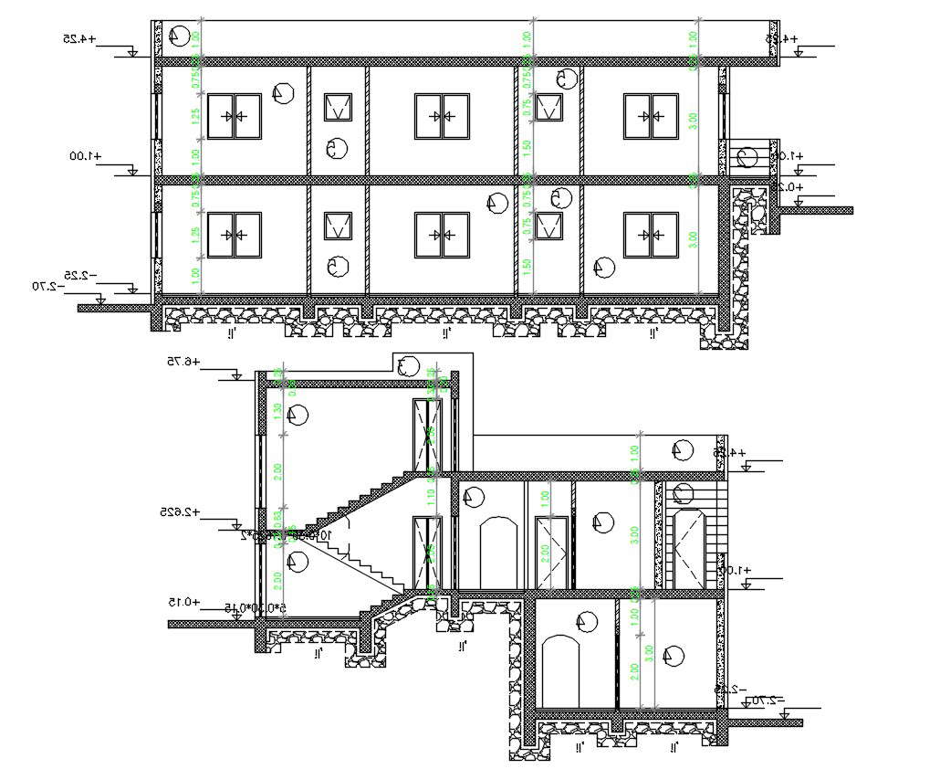
AutoCAD House Building Cross Section Drawing DWG File Cadbull

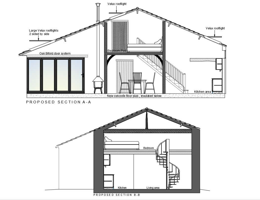
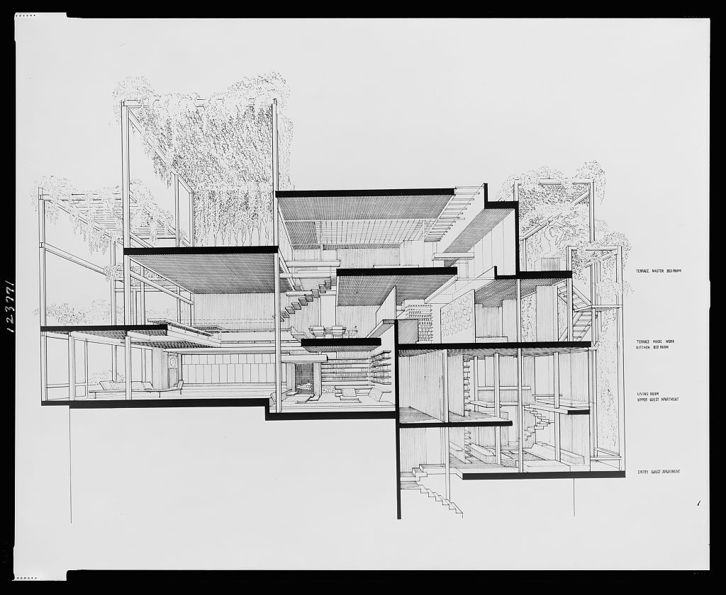
Cross Sections Drawings Residential Design Inc
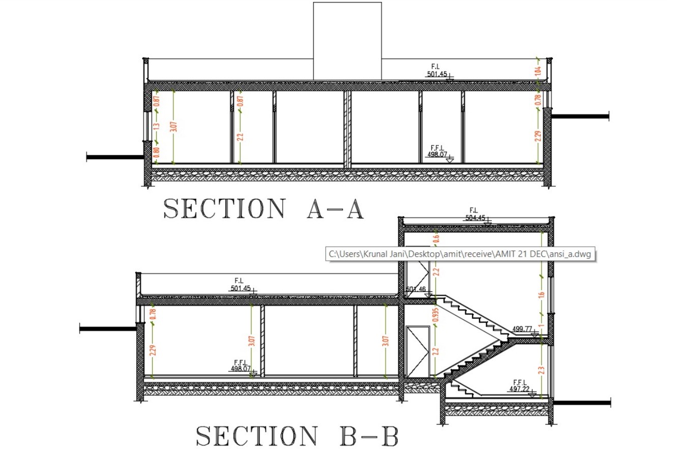
House Building Cross Section Drawing DWG File Cadbull
House Cross Section Drawing Cadbull

How to Draw House Cross Sections

How to Draw House Cross Sections
14 House Cross Section Drawing That Will Bring The Joy Home Plans

How to Draw House Cross Sections
Section Drawing Architecture at Explore collection
The Section Plane Lies Perpendicular To A Longitudinal Section, And It’s Used To Show The Inside Of A Building The Same Way.
The Cross Section Of A Rectangular Pyramid Is A Rectangle.
Published On August 29, 2019.
This Tutorial Is On How To Draw A Cross Section Or Profile From A Given Point To Another.
Related Post: