761 Draw The Shear And Moment Diagrams For The Beam
761 Draw The Shear And Moment Diagrams For The Beam - We are given the load p = 10 kn/m p = 10 k n / m, moment m = 20 kn⋅ m m = 20 k n ⋅ m and force is f = 15 kn f = 15 k n. 200lb 100lb 250lb 100lb 0 250 lbrc Web there are 4 steps to solve this one. Determine all the reactions on the beam. Web in order to construct shear and moment diagrams for a beam, first, determine the reactive forces and couple moments acting on the beam, and resolve all the forces into. This is an example problem that will show you how to graphically draw a shear and moment diagram for a. Figures 1 through 32 provide a series of shear and moment diagrams with accompanying formulas for design of beams under various static loading. Download a customised selection of the. You'll get a detailed solution from a subject matter expert that helps you learn core concepts. We are asked to draw. We go through breaking a beam into segments, and. 42k views 2 years ago statics. M = fc ⋅ z = ft ⋅ z where fc = ft = σ 2 ⋅ a 2 = σ ⋅ a 4. Learn to draw shear force and moment diagrams using 2 methods, step by step. 90k views 3 years ago statics. The shear force at any. Write shear and moment equations for the beams in the following problems. 291k views 2 years ago engineering statics. Web there are 4 steps to solve this one. Web the bending moment is given by: Web in order to construct shear and moment diagrams for a beam, first, determine the reactive forces and couple moments acting on the beam, and resolve all the forces into. You'll get a detailed solution from a subject matter expert that helps you learn core concepts. Write shear and moment equations for the beams in the following problems. Figures 1. Web shearing force diagram. M = fc ⋅ z = ft ⋅ z where fc = ft = σ 2 ⋅ a 2 = σ ⋅ a 4. Web in order to construct shear and moment diagrams for a beam, first, determine the reactive forces and couple moments acting on the beam, and resolve all the forces into. Divide the. Shear and bending moment equations. 90k views 3 years ago statics. Web shearing force diagram. What you need to calculate them. Web in order to construct shear and moment diagrams for a beam, first, determine the reactive forces and couple moments acting on the beam, and resolve all the forces into. Download a customised selection of the. 200lb 100lb 250lb 100lb 0 250 lbrc Loads applied to the beam may consist of a concentrated load (load applied at a point), uniform load, uniformly varying load, or an applied couple or. Figures 1 through 32 provide a series of shear and moment diagrams with accompanying formulas for design of beams under various. Download a customised selection of the. In each problem, let x be the distance measured from left end of the beam. Learn to draw shear force and moment diagrams using 2 methods, step by step. The shear force at any. Divide the beam (of length l) into n segments. 291k views 2 years ago engineering statics. Web write equations for the shear v and bending moment m for any section of the beam in the interval ab. Web draw the shear and moment diagrams for the beam 6 kn 8 kn/m 1.5 m 1.5 m prob. We go through breaking a beam into segments, and. 6.2.3 producing a shear/moment. 6.2.3 producing a shear/moment diagram. This is an example problem that will show you how to graphically draw a shear and moment diagram for a. Write shear and moment equations for the beams in the following problems. Figures 1 through 32 provide a series of shear and moment diagrams with accompanying formulas for design of beams under various static loading.. Download a customised selection of the. We go through breaking a beam into segments, and. M = fc ⋅ z = ft ⋅ z where fc = ft = σ 2 ⋅ a 2 = σ ⋅ a 4. What you need to calculate them. Loads applied to the beam may consist of a concentrated load (load applied at a. You'll get a detailed solution from a subject matter. 291k views 2 years ago engineering statics. What you need to calculate them. 42k views 2 years ago statics. Web draw the shear and moment diagrams for the beam 6 kn 8 kn/m 1.5 m 1.5 m prob. Figures 1 through 32 provide a series of shear and moment diagrams with accompanying formulas for design of beams under various static loading. Loads applied to the beam may consist of a concentrated load (load applied at a point), uniform load, uniformly varying load, or an applied couple or. This section will discuss three related but different methods to produce shear and bending moment diagrams, and conclude with a comparison of the advantages and. In each problem, let x be the distance measured from left end of the beam. We are asked to draw. Web the bending moment is given by: Divide the beam (of length l) into n segments. We are given the load p = 10 kn/m p = 10 k n / m, moment m = 20 kn⋅ m m = 20 k n ⋅ m and force is f = 15 kn f = 15 k n. Web shearing force diagram. Shear and bending moment diagrams: Learn to draw shear force and moment diagrams using 2 methods, step by step.Draw The Shear Diagram For The Beam Wiring Site Resource
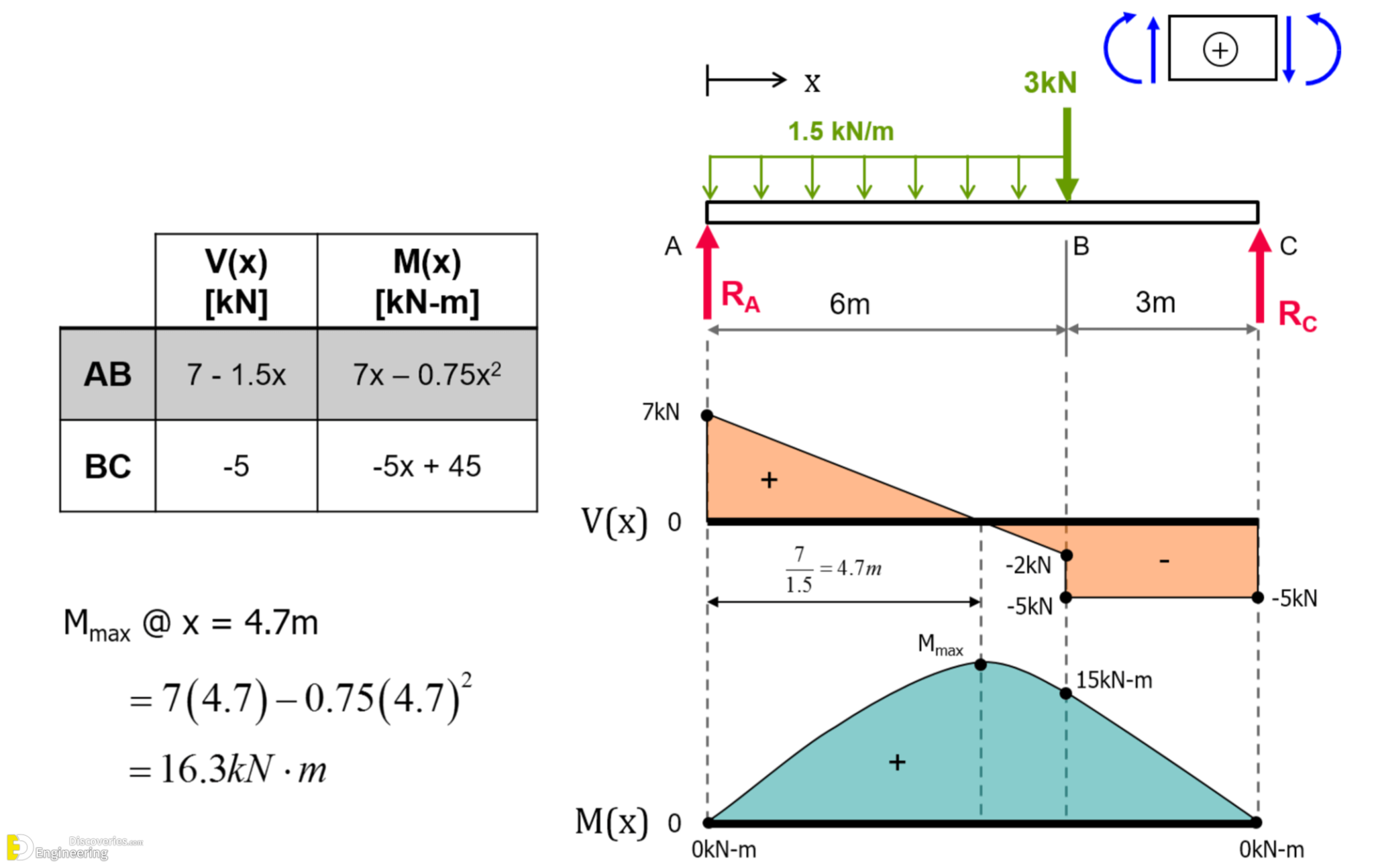
Learn How To Draw Shear Force And Bending Moment Diagrams Engineering
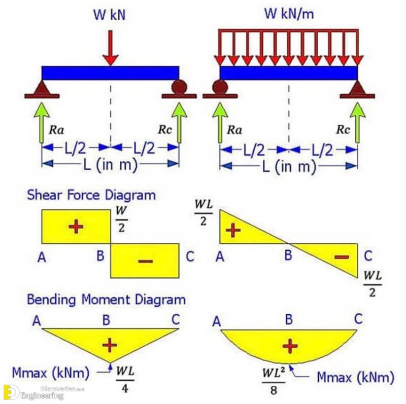
Brief Information About Shear Force And Bending Moment Diagrams
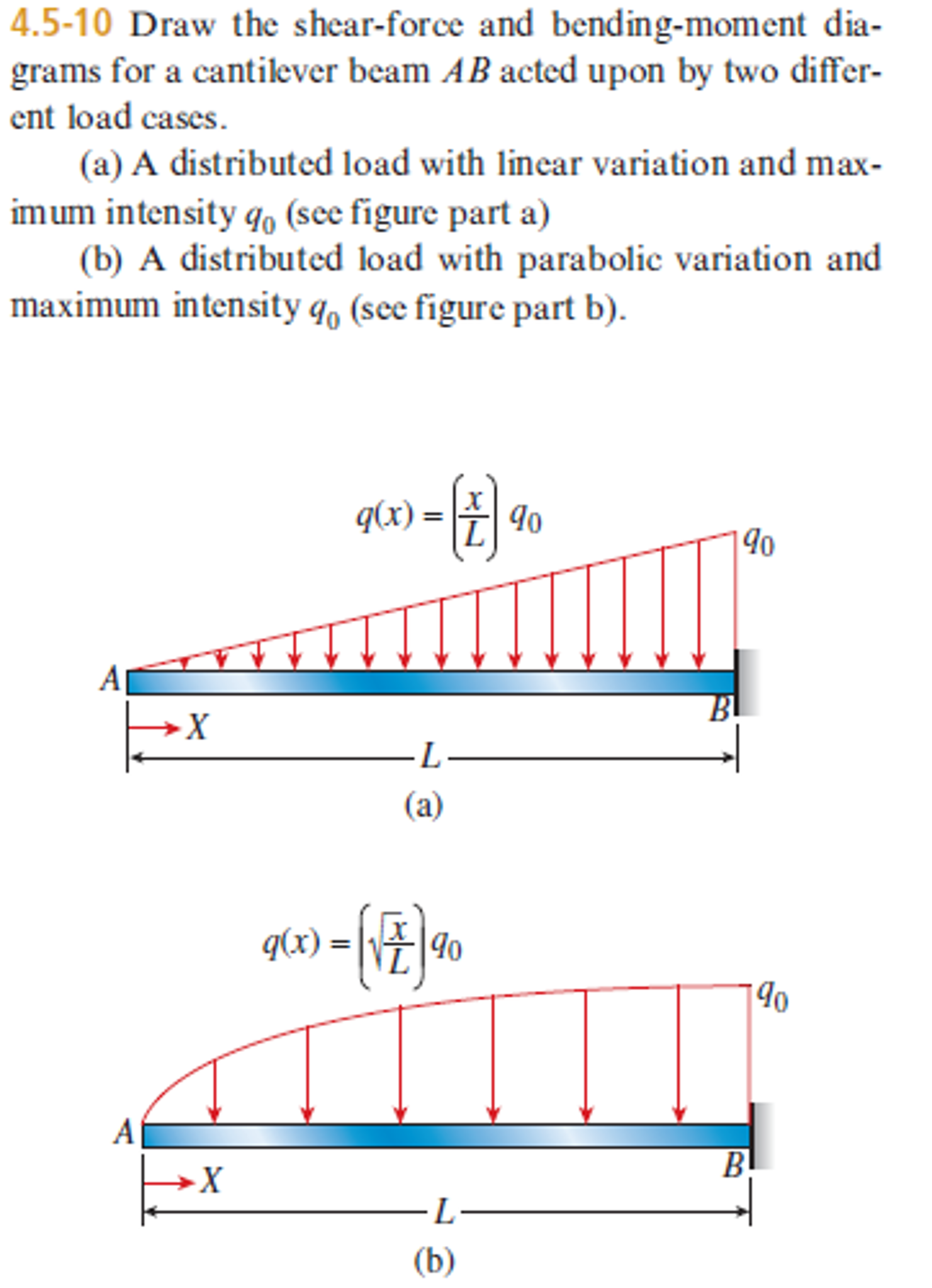
Shear And Moment Diagrams For Beams
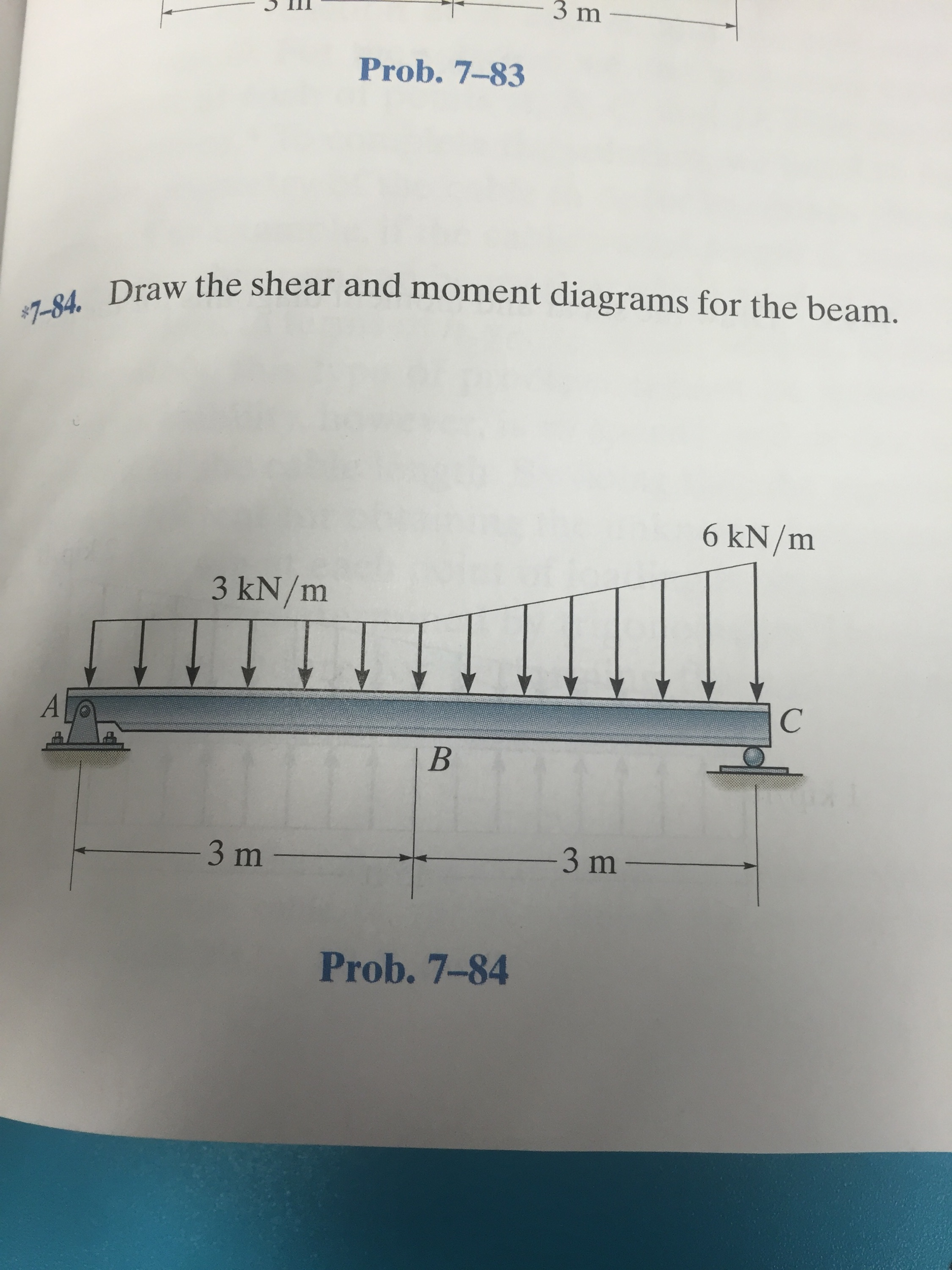
Solved Draw the shear and moment diagrams for the beam.

Solved Draw the shear and moment diagrams for the beam

Learn How To Draw Shear Force And Bending Moment Diagrams Engineering

Solved Draw the shear and moment diagrams for the beam.
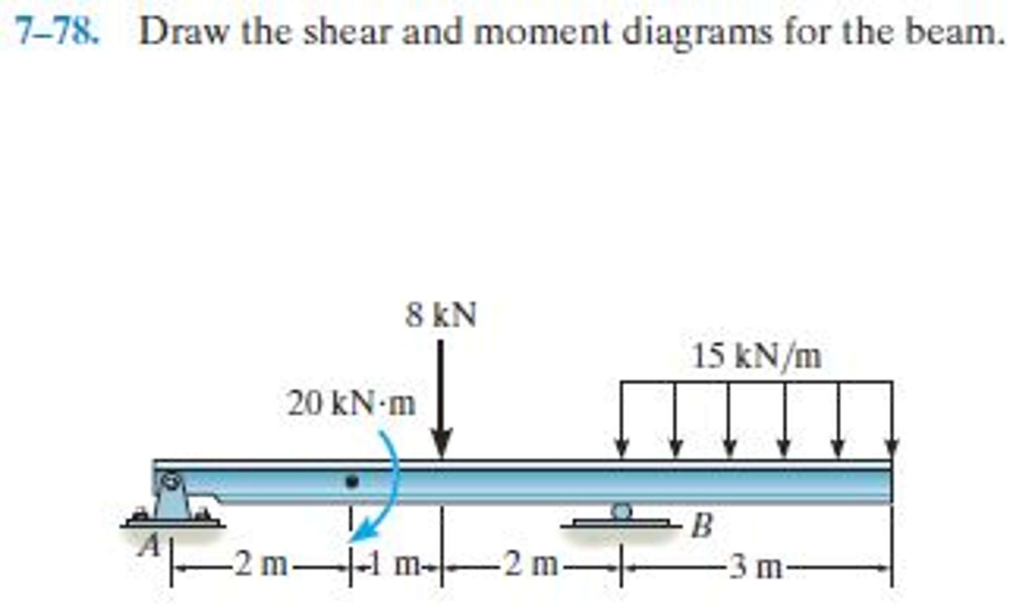
Draw the shear and moment diagrams for the beam.
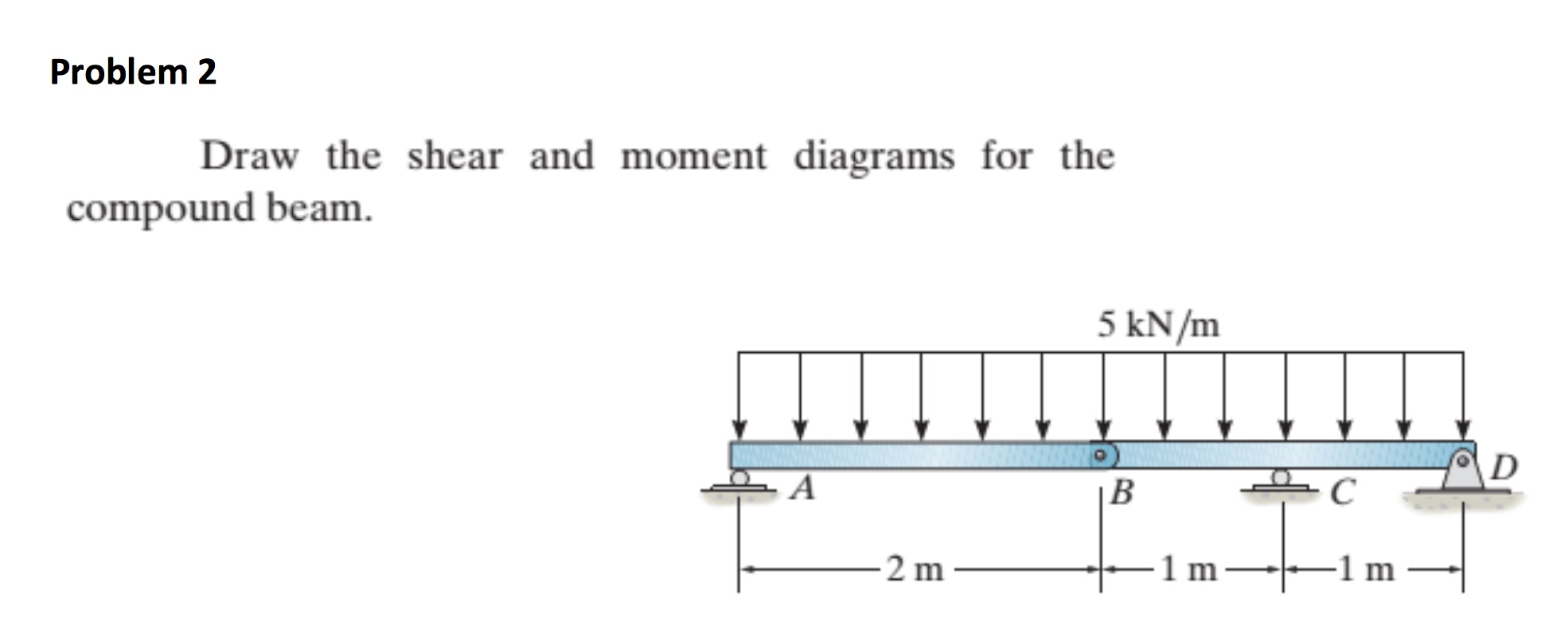
draw the shear and moment diagrams for the beam chegg
We Go Through Breaking A Beam Into Segments, And.
Web In Order To Construct Shear And Moment Diagrams For A Beam, First, Determine The Reactive Forces And Couple Moments Acting On The Beam, And Resolve All The Forces Into.
Web Write Equations For The Shear V And Bending Moment M For Any Section Of The Beam In The Interval Ab.
Determine All The Reactions On The Beam.
Related Post:
